
How to Use TB6600: Examples, Pinouts, and Specs
 Design with TB6600 in Cirkit Designer
Introduction
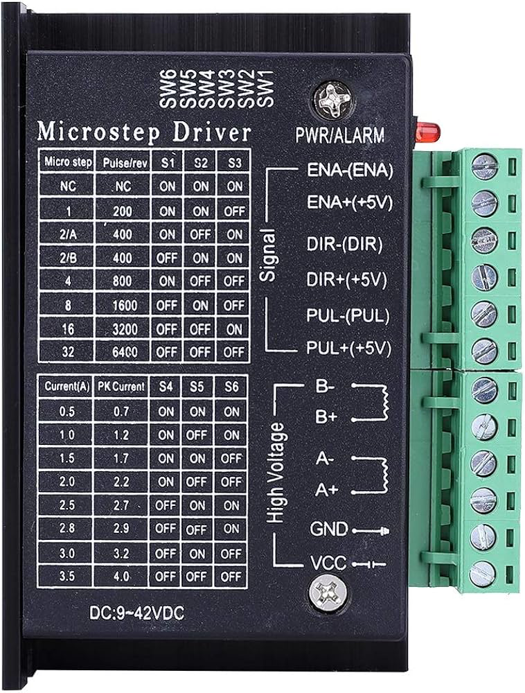
The TB6600 is a high-performance microstepping driver designed for bipolar stepper motors. Manufactured by Tvoja Manka, this driver is capable of delivering up to 4.5A of current per phase, making it suitable for driving medium to high-power stepper motors. It features adjustable current control, multiple microstepping options, and built-in protection mechanisms, ensuring smooth operation and precise positioning. The TB6600 is widely used in CNC machines, 3D printers, robotics, and other motion control applications.
Explore Projects Built with TB6600
 Open Project in Cirkit Designer
 Open Project in Cirkit Designer
 Open Project in Cirkit Designer
 Open Project in Cirkit Designer
Explore Projects Built with TB6600
Open Project in Cirkit DesignerOpen Project in Cirkit DesignerOpen Project in Cirkit DesignerOpen Project in Cirkit DesignerCommon Applications
- CNC machines for precise cutting and engraving
- 3D printers for accurate layer positioning
- Robotics for controlled motion
- Automated machinery and conveyor systems
- DIY projects requiring stepper motor control
Technical Specifications
Key Technical Details
| Parameter | Value |
|---|---|
| Manufacturer | Tvoja Manka |
| Part ID | TB6600 |
| Motor Type Supported | Bipolar Stepper Motors |
| Operating Voltage Range | 9V to 42V DC |
| Maximum Output Current | 4.5A per phase |
| Microstepping Options | Full, 1/2, 1/4, 1/8, 1/16 |
| Control Signal Voltage | 3.3V to 5V (compatible with Arduino, etc.) |
| Input Signal Types | Pulse (PUL+/-), Direction (DIR+/-), Enable (ENA+/-) |
| Protection Features | Overcurrent, Overheat, and Short Circuit |
| Dimensions | 96mm x 56mm x 33mm |
Pin Configuration and Descriptions
The TB6600 driver has several input and output terminals for motor control and power connections. Below is the pin configuration:
Input Signal Pins
| Pin Name | Description |
|---|---|
| PUL+ | Pulse signal positive input (step signal) |
| PUL- | Pulse signal negative input |
| DIR+ | Direction signal positive input |
| DIR- | Direction signal negative input |
| ENA+ | Enable signal positive input (optional) |
| ENA- | Enable signal negative input (optional) |
Power and Motor Connection Pins
| Pin Name | Description |
|---|---|
| VCC | Power supply positive terminal (9V to 42V DC) |
| GND | Power supply ground terminal |
| A+ | Motor coil A positive terminal |
| A- | Motor coil A negative terminal |
| B+ | Motor coil B positive terminal |
| B- | Motor coil B negative terminal |
Usage Instructions
Connecting the TB6600 to a Stepper Motor
- Power Supply: Connect a DC power supply (9V to 42V) to the
VCCandGNDterminals. Ensure the power supply can provide sufficient current for your motor. - Motor Connections: Connect the stepper motor's coils to the
A+,A-,B+, andB-terminals. Refer to your motor's datasheet to identify the coil pairs. - Control Signals: Connect the
PUL+,PUL-,DIR+,DIR-, and optionallyENA+,ENA-pins to your microcontroller or control board (e.g., Arduino UNO). - Microstepping and Current Settings: Use the DIP switches on the TB6600 to configure the desired microstepping mode and current limit. Refer to the TB6600 datasheet for DIP switch settings.
Example: Using the TB6600 with an Arduino UNO
Below is an example Arduino sketch to control a stepper motor using the TB6600:
// Define control pins for the TB6600
#define PUL_PIN 2  // Pulse signal pin
#define DIR_PIN 3  // Direction signal pin

void setup() {
  // Set control pins as outputs
  pinMode(PUL_PIN, OUTPUT);
  pinMode(DIR_PIN, OUTPUT);

  // Set initial direction
  digitalWrite(DIR_PIN, HIGH); // HIGH for one direction, LOW for the other
}

void loop() {
  // Generate pulses to move the stepper motor
  digitalWrite(PUL_PIN, HIGH); // Set pulse pin HIGH
  delayMicroseconds(500);      // Wait for 500 microseconds
  digitalWrite(PUL_PIN, LOW);  // Set pulse pin LOW
  delayMicroseconds(500);      // Wait for 500 microseconds
}
Important Considerations
- Current Settings: Ensure the current limit is set appropriately for your motor to prevent overheating or damage.
- Cooling: The TB6600 can get hot during operation. Use a heatsink or active cooling if necessary.
- Signal Voltage: Ensure the control signal voltage (3.3V or 5V) matches the requirements of the TB6600.
- Wiring: Double-check all connections before powering on the driver to avoid short circuits or damage.
Troubleshooting and FAQs
Common Issues and Solutions
Motor Not Moving
- Cause: Incorrect wiring or no pulse signal.
- Solution: Verify motor coil connections and ensure the control signals are being sent correctly.
Motor Vibrates but Does Not Rotate
- Cause: Incorrect microstepping or current settings.
- Solution: Check and adjust the DIP switch settings for microstepping and current.
Driver Overheating
- Cause: Insufficient cooling or excessive current.
- Solution: Add a heatsink or fan, and reduce the current limit if necessary.
Motor Moves in the Wrong Direction
- Cause: Incorrect direction signal or swapped motor coil connections.
- Solution: Reverse the
DIRsignal or swap the connections of one motor coil.
No Power to the Driver
- Cause: Faulty power supply or loose connections.
- Solution: Check the power supply voltage and ensure all connections are secure.
FAQs
Can the TB6600 drive unipolar stepper motors? No, the TB6600 is designed specifically for bipolar stepper motors.
What is the maximum step frequency supported? The TB6600 supports a maximum pulse frequency of 200 kHz.
Is the TB6600 compatible with 3.3V logic? Yes, the TB6600 is compatible with both 3.3V and 5V logic levels.
Can I use the TB6600 without the enable signal? Yes, the enable signal is optional. If not used, the driver will remain enabled by default.
How do I select the microstepping mode? Use the DIP switches on the driver to configure the microstepping mode. Refer to the TB6600 datasheet for detailed settings.
This concludes the documentation for the TB6600 stepper motor driver. For further assistance, refer to the manufacturer's datasheet or contact Tvoja Manka support.