How to Use usb-breadboard: Examples, Pinouts, and Specs
Introduction
A USB breadboard is an essential tool for prototyping and testing electronic circuits. It provides a convenient platform for engineers, hobbyists, and educators to quickly assemble and modify circuits without the need for soldering. The USB breadboard typically includes a USB interface for power supply and/or data communication, making it ideal for developing USB-powered devices, microcontroller-based projects, and interactive hardware prototypes.
Explore Projects Built with usb-breadboard


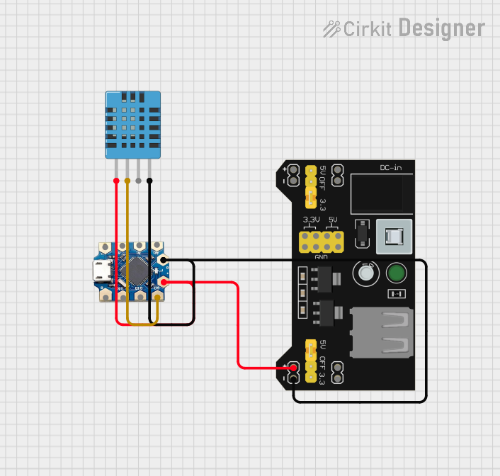
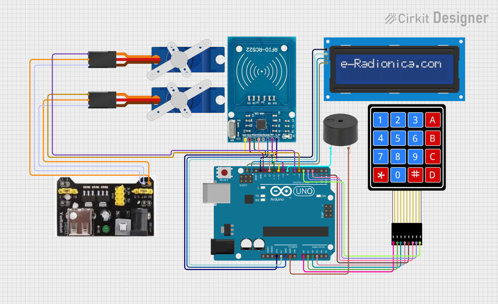
Explore Projects Built with usb-breadboard
Common Applications and Use Cases
- Rapid prototyping of electronic circuits
- Educational purposes for learning circuit design
- Testing and debugging USB-powered devices
- Development of microcontroller-based projects (e.g., Arduino, Raspberry Pi)
- Interactive installations and maker projects
Technical Specifications
Key Technical Details
- Voltage Rating: 5V (typical USB power supply)
- Current Rating: Varies depending on the model (e.g., 500mA for USB 2.0)
- Power Ratings: Dependent on USB version and power source capabilities
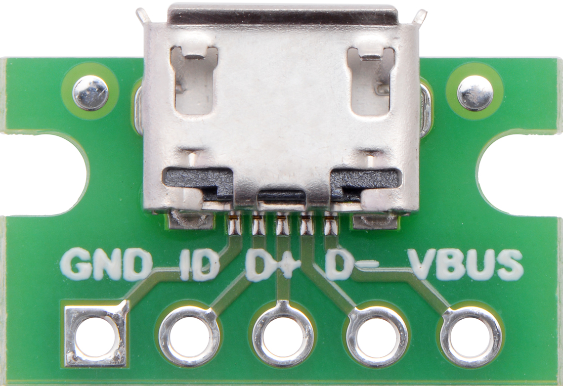
Pin Configuration and Descriptions
| Pin Number | Description | Notes |
|---|---|---|
| 1 | VBUS (Power Supply) | Typically 5V from USB |
| 2 | D- (Data Minus) | USB data line |
| 3 | D+ (Data Plus) | USB data line |
| 4 | GND (Ground) | Reference potential for circuit |
Usage Instructions
How to Use the Component in a Circuit
Powering the Breadboard:
- Connect the USB cable to the breadboard's USB port and to a power source (e.g., computer, USB charger).
- Verify that the power LED indicator (if available) is lit, indicating that the breadboard is powered.
Assembling a Circuit:
- Insert electronic components into the breadboard's holes, ensuring that they are firmly seated.
- Use jumper wires to make connections between components following your circuit design.
Testing and Iteration:
- Apply power to the circuit and observe its behavior.
- Make adjustments as necessary by adding, removing, or repositioning components and wires.
Important Considerations and Best Practices
- Current Limitations: Do not exceed the current rating of the breadboard or the USB power source.
- Short Circuits: Avoid creating short circuits, which can damage components and the breadboard.
- Component Orientation: Pay attention to the orientation of polarized components like diodes and capacitors.
- Wire Management: Keep wires organized to prevent confusion and reduce the risk of accidental shorts.
Troubleshooting and FAQs
Common Issues Users Might Face
- No Power: Ensure the USB cable is properly connected and the power source is on.
- Intermittent Connections: Check for loose wires or components and ensure they are inserted correctly.
- Overheating Components: Disconnect power immediately and check for short circuits or excessive current draw.
Solutions and Tips for Troubleshooting
- LED Indicators: Use LED indicators to help visualize power and signal flow in the circuit.
- Multimeter Use: Employ a multimeter to check for continuity, voltage levels, and current flow.
- Incremental Testing: Test sections of your circuit incrementally to isolate and identify issues.
FAQs
Q: Can I power my breadboard with a USB 3.0 port?
- A: Yes, USB 3.0 ports are backward compatible and can power the breadboard, often providing more current than USB 2.0.
Q: How do I know if my circuit is drawing too much current?
- A: Use a multimeter to measure the current draw. If it exceeds the breadboard or USB port's rating, you need to reduce the load.
Example Code for Arduino UNO
// Example code to blink an LED connected to an Arduino UNO on a USB breadboard

void setup() {
  pinMode(13, OUTPUT); // Set digital pin 13 as an output
}

void loop() {
  digitalWrite(13, HIGH); // Turn the LED on
  delay(1000);            // Wait for a second
  digitalWrite(13, LOW);  // Turn the LED off
  delay(1000);            // Wait for a second
}
Remember to connect the LED's anode (longer leg) to pin 13 and the cathode (shorter leg) to one of the GND pins on the breadboard. Use a resistor (e.g., 220 ohms) in series with the LED to limit current and prevent damage.