How to Use Sound Sensor: Examples, Pinouts, and Specs
Introduction
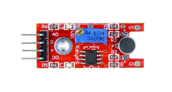
The Sound Sensor is a device designed to detect sound levels and convert them into electrical signals. It typically consists of a microphone, an amplifier, and a signal processing circuit. This component is widely used in applications such as voice recognition systems, noise monitoring, and interactive projects like sound-activated lighting or robotics.
Common use cases include:
- Detecting claps or voice commands in smart home systems.
- Monitoring environmental noise levels.
- Enabling sound-based interaction in Arduino or Raspberry Pi projects.
Explore Projects Built with Sound Sensor
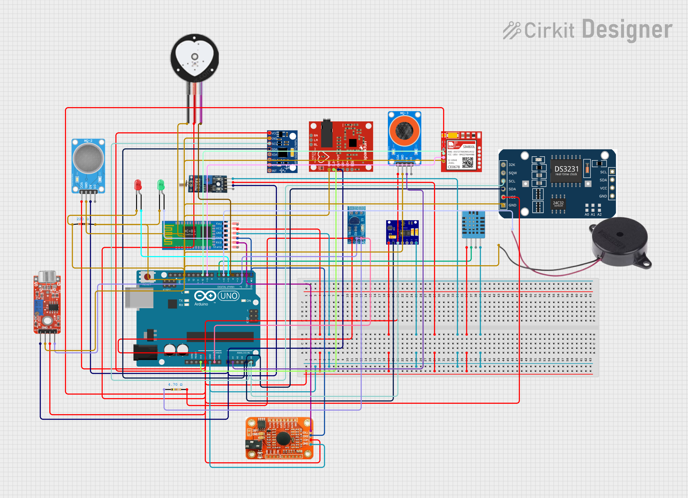
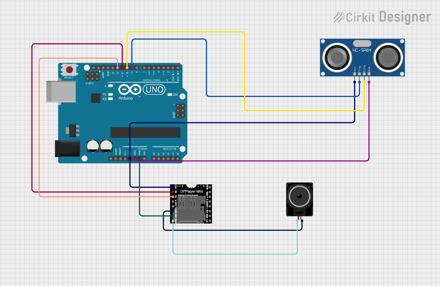
Explore Projects Built with Sound Sensor
Technical Specifications
Below are the key technical details of a typical sound sensor module:
| Parameter | Value |
|---|---|
| Operating Voltage | 3.3V to 5V |
| Output Type | Analog and Digital |
| Sensitivity Adjustment | Potentiometer (onboard) |
| Microphone Type | Electret Condenser Microphone |
| Dimensions | ~32mm x 15mm x 8mm |
| Operating Temperature | -40°C to +85°C |
Pin Configuration and Descriptions
| Pin Name | Description |
|---|---|
| VCC | Power supply pin (3.3V to 5V). Connect to the positive terminal of the power source. |
| GND | Ground pin. Connect to the ground of the circuit. |
| A0 | Analog output pin. Outputs a voltage proportional to the detected sound level. |
| D0 | Digital output pin. Outputs HIGH or LOW based on the sound threshold set via the potentiometer. |
Usage Instructions
How to Use the Sound Sensor in a Circuit
- Power the Sensor: Connect the
VCCpin to a 3.3V or 5V power source and theGNDpin to the ground. - Choose Output Type:
- Use the
A0pin for analog output to measure varying sound levels. - Use the
D0pin for digital output to detect sound above a set threshold.
- Use the
- Adjust Sensitivity: Use the onboard potentiometer to set the sensitivity for the digital output. Turning the potentiometer clockwise increases sensitivity.
- Connect to a Microcontroller: For example, connect the
A0orD0pin to an analog or digital input pin on an Arduino UNO.
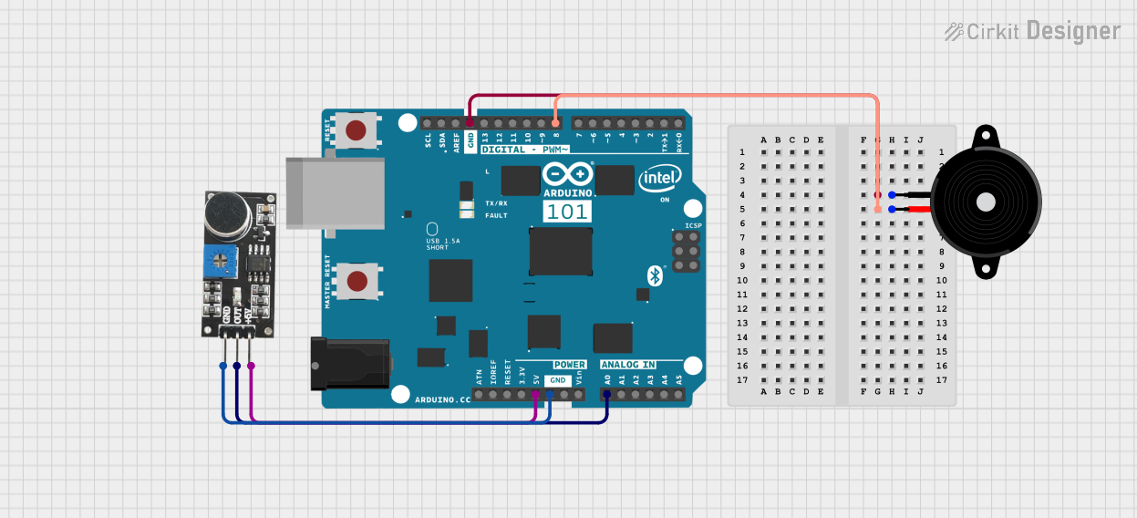
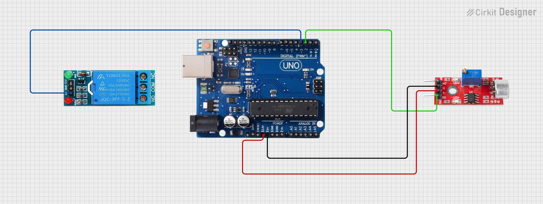
Example: Connecting to an Arduino UNO
Below is an example of how to use the sound sensor with an Arduino UNO to read both analog and digital outputs.
Circuit Connections
VCC→ 5V on ArduinoGND→ GND on ArduinoA0→ A0 on Arduino (for analog output)D0→ D2 on Arduino (for digital output)
Arduino Code
// Sound Sensor Example Code
// Reads analog and digital outputs from the sound sensor and prints the values.

const int analogPin = A0;  // Pin connected to the analog output (A0)
const int digitalPin = 2;  // Pin connected to the digital output (D0)

void setup() {
  Serial.begin(9600);      // Initialize serial communication at 9600 baud
  pinMode(digitalPin, INPUT); // Set digital pin as input
}

void loop() {
  int analogValue = analogRead(analogPin); // Read analog value from A0
  int digitalValue = digitalRead(digitalPin); // Read digital value from D0

  // Print the values to the Serial Monitor
  Serial.print("Analog Value: ");
  Serial.print(analogValue);
  Serial.print(" | Digital Value: ");
  Serial.println(digitalValue);

  delay(500); // Wait for 500ms before the next reading
}
Important Considerations and Best Practices
- Power Supply: Ensure the sensor is powered within its operating voltage range (3.3V to 5V).
- Noise Interference: Avoid placing the sensor near high-frequency noise sources, as this may affect its accuracy.
- Sensitivity Adjustment: Fine-tune the potentiometer to achieve the desired sensitivity for your application.
- Signal Stability: Use capacitors or filters if the analog output signal is too noisy for your application.
Troubleshooting and FAQs
Common Issues and Solutions
No Output from the Sensor:
- Check the power connections to ensure the sensor is receiving the correct voltage.
- Verify that the ground connection is secure.
Digital Output Always HIGH or LOW:
- Adjust the potentiometer to set an appropriate sound threshold.
- Ensure the sound level in the environment is within the sensor's detection range.
Analog Output is Unstable:
- Use a capacitor across the analog output pin and ground to filter noise.
- Ensure the sensor is not exposed to excessive vibrations or electrical interference.
Sensor Not Responding to Sound:
- Confirm that the microphone is not obstructed or damaged.
- Test the sensor in a quieter environment to rule out background noise interference.
FAQs
Q: Can the sound sensor detect specific frequencies?
A: No, the sound sensor is designed to detect overall sound levels and cannot differentiate between specific frequencies.
Q: How do I increase the detection range of the sensor?
A: You can increase the sensitivity by adjusting the potentiometer, but note that this may also make the sensor more prone to noise.
Q: Can I use the sound sensor outdoors?
A: While the sensor can operate in a wide temperature range, it is not waterproof. Use a protective enclosure if deploying it outdoors.
Q: What is the difference between the analog and digital outputs?
A: The analog output provides a continuous voltage proportional to the sound level, while the digital output provides a HIGH or LOW signal based on the set threshold.