How to Use Directional Switch: Examples, Pinouts, and Specs
Introduction
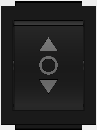
A Directional Switch is an electronic component that allows for the control of current flow within a circuit. It can be toggled or actuated to redirect the flow of current to different paths, making it an essential component in various applications such as:
- Selection of output lines in communication systems
- Control of motors or other actuators in robotics
- User input for control panels and interfaces
- Switching between different power sources or signal paths
Explore Projects Built with Directional Switch
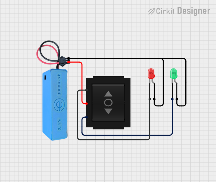
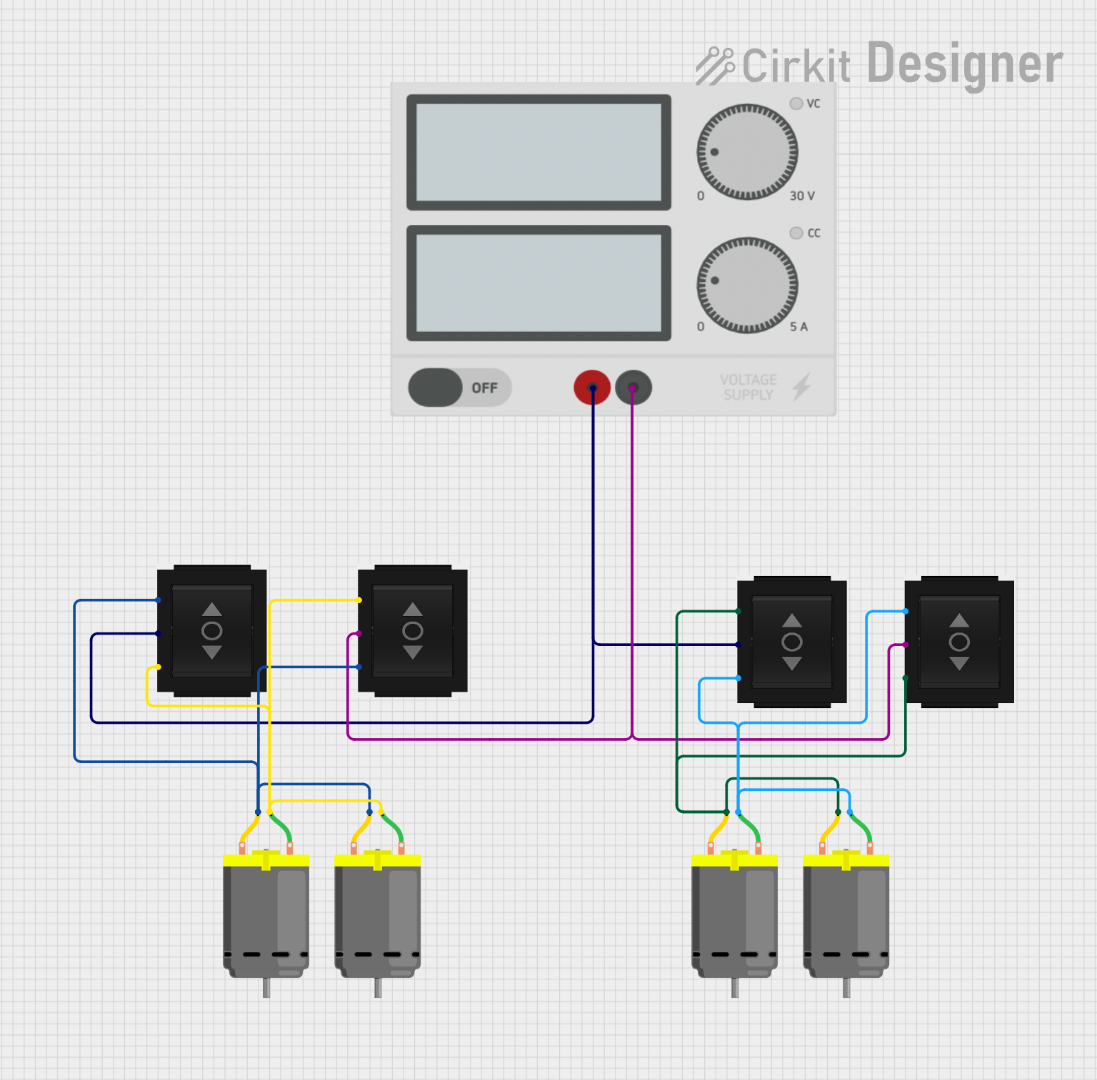
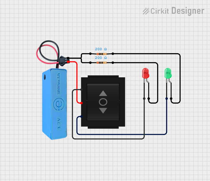
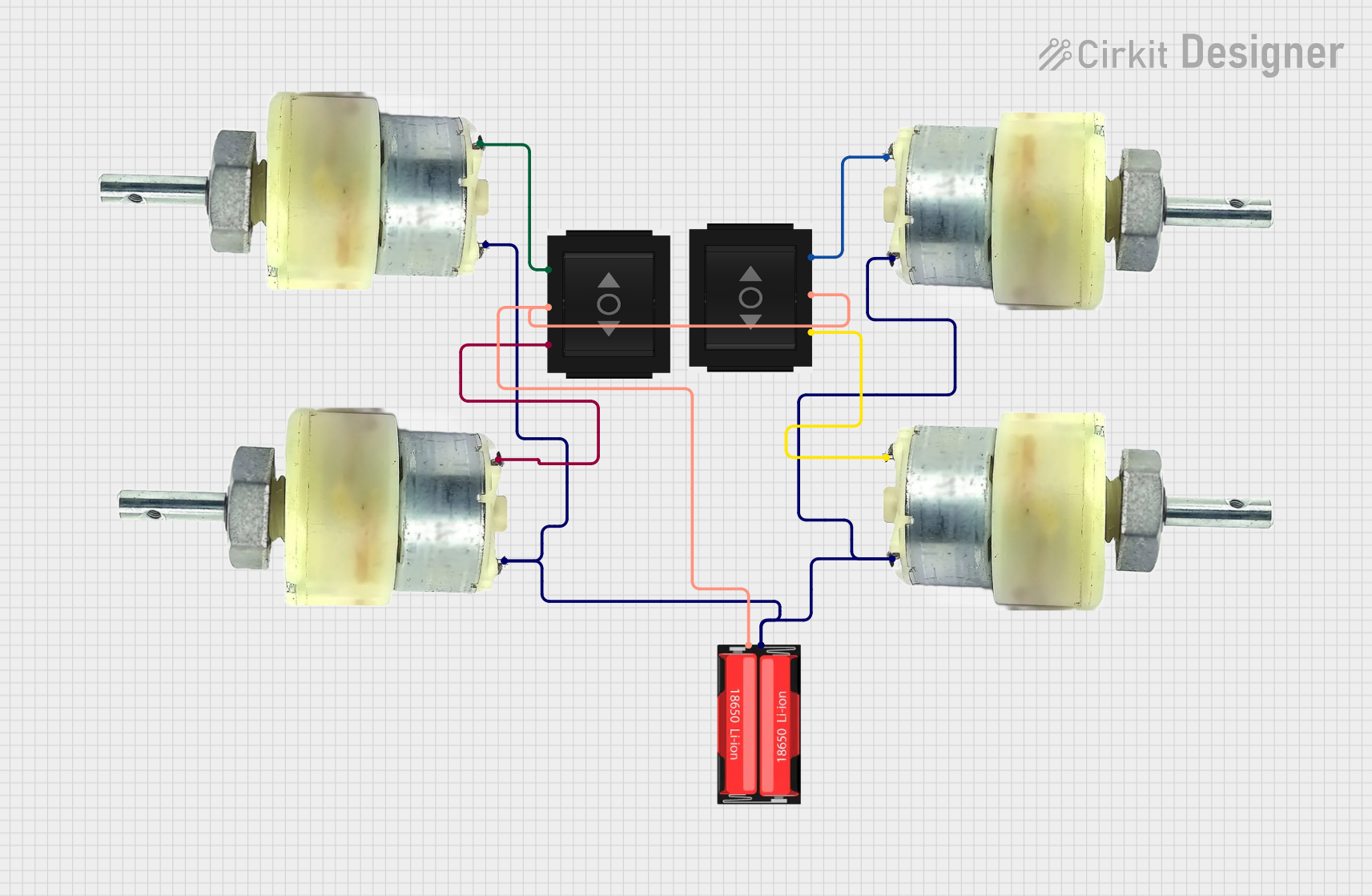
Explore Projects Built with Directional Switch
Technical Specifications
Key Technical Details
- Voltage Rating: The maximum voltage the switch can handle.
- Current Rating: The maximum current the switch can conduct.
- Power Rating: The total power capacity of the switch.
- Contact Resistance: The resistance between the contacts when the switch is closed.
- Insulation Resistance: The resistance between the contacts and the body of the switch.
- Mechanical Life: The number of actuations the switch can withstand before failure.
Pin Configuration and Descriptions
| Pin Number | Description | Notes |
|---|---|---|
| 1 | Common Pole | Connects to the circuit's input |
| 2 | Normally Open (NO) | Connects to the first path |
| 3 | Normally Closed (NC) | Connects to the second path |
Usage Instructions
How to Use the Directional Switch in a Circuit
- Identify the Pins: Refer to the pin configuration table to identify the Common Pole, Normally Open, and Normally Closed pins.
- Circuit Integration: Connect the Common Pole to the point in the circuit where you want to control the current flow.
- Path Selection: Connect the Normally Open and Normally Closed pins to the respective paths you wish to switch between.
- Actuation: Use a toggle or actuator to change the switch's position, thereby redirecting the current flow.
Important Considerations and Best Practices
- Voltage and Current Ratings: Ensure that the switch's ratings are suitable for the circuit's voltage and current to prevent damage.
- Debouncing: If the switch is used for digital signal control, implement debouncing either through hardware or software to avoid erratic signals.
- Mounting: Secure the switch firmly to avoid any movement that could lead to intermittent connections.
- Wiring: Use wires with appropriate insulation and thickness to handle the expected current.
Troubleshooting and FAQs
Common Issues
- Intermittent Operation: Check for loose connections or damage to the switch.
- Overheating: Ensure the current and voltage do not exceed the switch's ratings.
- No Current Flow: Verify that the switch is in the correct position and that there are no breaks in the circuit.
Solutions and Tips for Troubleshooting
- Secure Connections: Tighten any loose terminals or solder points.
- Replace if Necessary: If the switch is damaged or has reached the end of its mechanical life, replace it with a new one.
- Test with a Multimeter: Use a multimeter to check for continuity when the switch is in different positions.
FAQs
Q: Can I use the directional switch with an Arduino UNO? A: Yes, the directional switch can be used with an Arduino UNO to control the flow of current to different parts of a circuit.
Q: How do I know if my directional switch is working correctly? A: You can test the switch using a multimeter to check for continuity or by observing the behavior of the circuit when the switch is actuated.
Q: What should I do if the switch is not switching properly? A: Check for any physical obstructions, ensure the switch is properly mounted, and verify that the electrical connections are secure.
Example Arduino UNO Code
Below is an example code snippet for using a directional switch with an Arduino UNO to control an LED:
// Define the pin numbers
const int switchPin = 2; // The pin where the switch is connected
const int ledPin = 13;   // The pin where the LED is connected

void setup() {
  pinMode(switchPin, INPUT_PULLUP); // Set the switch pin as an input with an internal pull-up resistor
  pinMode(ledPin, OUTPUT);          // Set the LED pin as an output
}

void loop() {
  // Read the state of the switch
  bool switchState = digitalRead(switchPin);

  // If the switch is closed, turn on the LED
  if (switchState == LOW) {
    digitalWrite(ledPin, HIGH);
  } else {
    // If the switch is open, turn off the LED
    digitalWrite(ledPin, LOW);
  }
}
In this example, the directional switch is connected to pin 2, and the LED to pin 13. When the switch is closed, the LED turns on; when the switch is open, the LED turns off. The INPUT_PULLUP mode is used to enable the internal pull-up resistor, which ensures a default high state when the switch is open.