How to Use bl 51: Examples, Pinouts, and Specs
Introduction
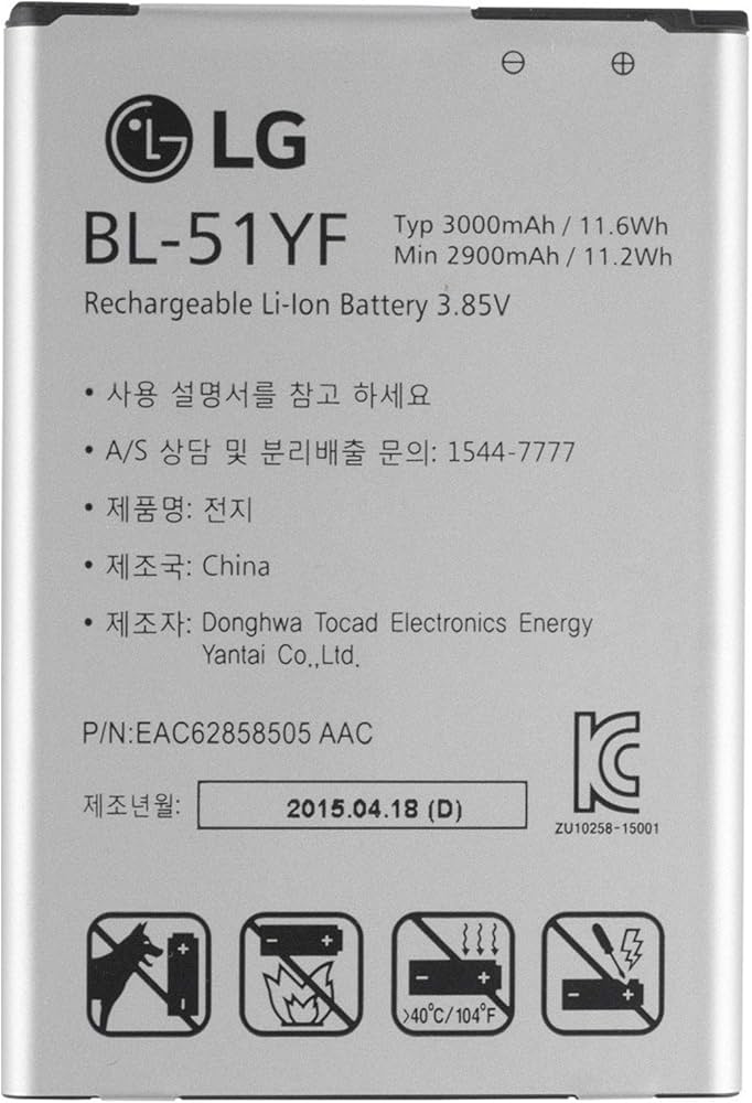
The BL 51, manufactured by LG, is a low-power, high-efficiency LED driver designed to power LED arrays in a wide range of applications. It provides a constant current output, ensuring optimal performance and longevity of connected LEDs. The BL 51 is ideal for applications requiring energy-efficient lighting solutions, such as residential lighting, commercial displays, and automotive lighting systems.
Explore Projects Built with bl 51
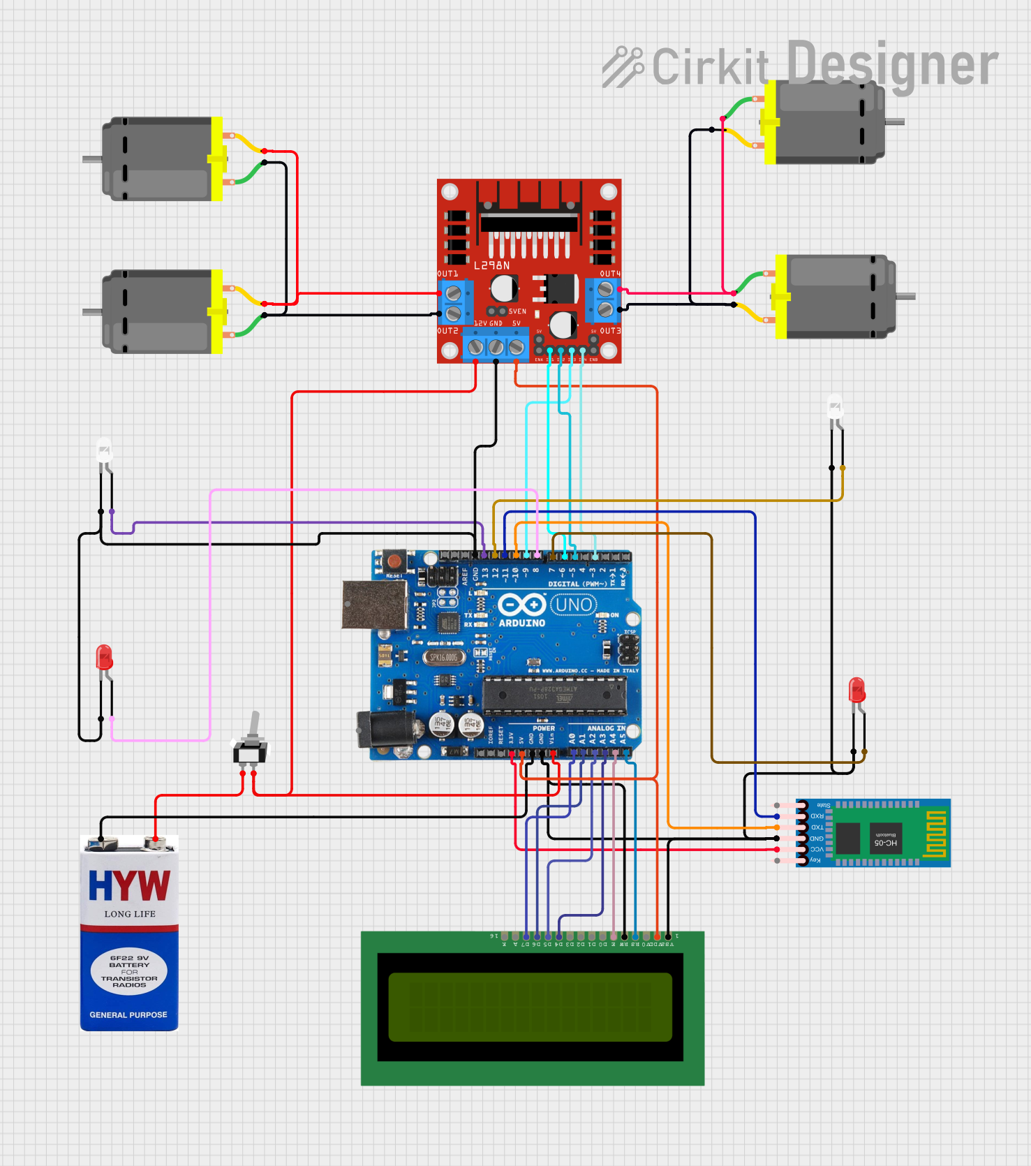
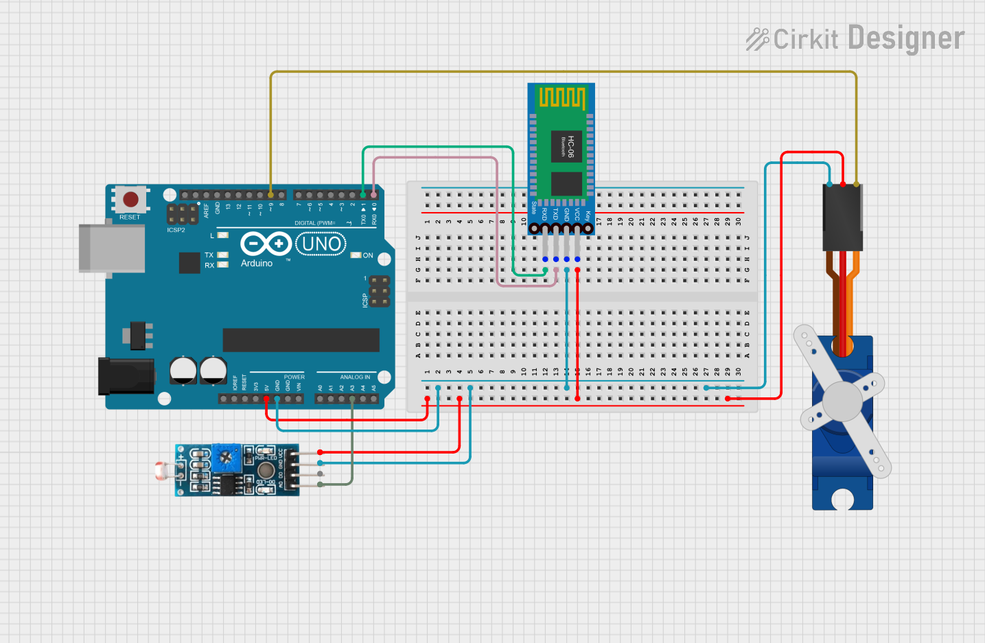
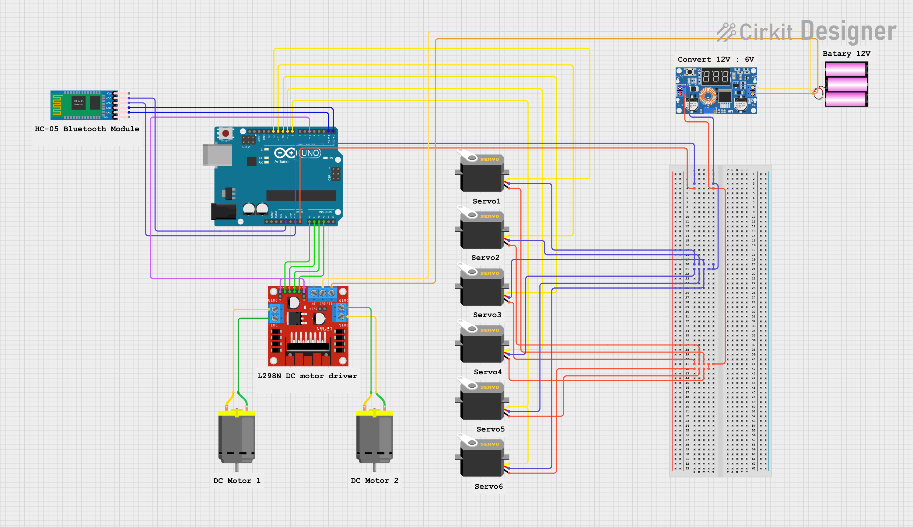
Explore Projects Built with bl 51
Common Applications
- Residential and commercial LED lighting
- Automotive interior and exterior lighting
- LED signage and displays
- Industrial lighting systems
Technical Specifications
Key Specifications
| Parameter | Value |
|---|---|
| Input Voltage Range | 6V to 24V |
| Output Current | 350mA (constant current) |
| Output Voltage Range | 2V to 20V |
| Efficiency | Up to 90% |
| Operating Temperature | -40°C to +85°C |
| Dimming Support | PWM and Analog Dimming |
| Package Type | SOT-23-6 |
Pin Configuration
The BL 51 is housed in a compact SOT-23-6 package. Below is the pin configuration:
| Pin Number | Pin Name | Description |
|---|---|---|
| 1 | VIN | Input voltage pin (6V to 24V) |
| 2 | GND | Ground pin |
| 3 | EN | Enable pin (active high) |
| 4 | DIM | Dimming control pin (PWM or analog input) |
| 5 | LED+ | Positive terminal for LED connection |
| 6 | LED- | Negative terminal for LED connection (current sink) |
Usage Instructions
How to Use the BL 51 in a Circuit
- Power Supply: Connect a DC power supply (6V to 24V) to the
VINpin andGNDpin. - LED Connection: Connect the positive terminal of the LED array to the
LED+pin and the negative terminal to theLED-pin. - Enable Pin: To activate the driver, apply a high signal (logic level) to the
ENpin. Pulling this pin low will disable the driver. - Dimming Control:
- For PWM dimming, apply a PWM signal (frequency range: 100Hz to 10kHz) to the
DIMpin. - For analog dimming, apply a DC voltage (0V to 2.5V) to the
DIMpin. A higher voltage corresponds to higher brightness.
- For PWM dimming, apply a PWM signal (frequency range: 100Hz to 10kHz) to the
- Current Regulation: The BL 51 automatically regulates the current to 350mA, ensuring consistent LED brightness.
Important Considerations
- Thermal Management: Ensure adequate heat dissipation, especially in high-power applications. Use a heatsink or place the component on a PCB with good thermal conductivity.
- Input Voltage: Do not exceed the maximum input voltage of 24V to avoid damaging the component.
- Dimming Signal: Ensure the dimming signal is within the specified range to prevent erratic behavior or damage.
- Bypass Capacitor: Place a bypass capacitor (e.g., 10µF) close to the
VINpin to stabilize the input voltage and reduce noise.
Example: Connecting the BL 51 to an Arduino UNO
The BL 51 can be controlled using an Arduino UNO for PWM dimming. Below is an example circuit and code:
Circuit Connections
- Connect the
VINpin of the BL 51 to the 5V output of the Arduino. - Connect the
GNDpin of the BL 51 to the GND of the Arduino. - Connect the
DIMpin of the BL 51 to a PWM-capable pin on the Arduino (e.g., Pin 9). - Connect the LED array to the
LED+andLED-pins of the BL 51.
Arduino Code
// Example code to control the BL 51 LED driver using PWM dimming
// Connect the DIM pin of the BL 51 to Pin 9 of the Arduino UNO

const int dimPin = 9; // PWM-capable pin connected to the DIM pin of BL 51

void setup() {
  pinMode(dimPin, OUTPUT); // Set the DIM pin as an output
}

void loop() {
  // Gradually increase brightness
  for (int brightness = 0; brightness <= 255; brightness++) {
    analogWrite(dimPin, brightness); // Write PWM signal to DIM pin
    delay(10); // Small delay for smooth transition
  }

  // Gradually decrease brightness
  for (int brightness = 255; brightness >= 0; brightness--) {
    analogWrite(dimPin, brightness); // Write PWM signal to DIM pin
    delay(10); // Small delay for smooth transition
  }
}
Troubleshooting and FAQs
Common Issues and Solutions
| Issue | Possible Cause | Solution |
|---|---|---|
| LEDs do not light up | Incorrect wiring or loose connections | Verify all connections and wiring. |
| LEDs flicker during operation | Unstable input voltage or noisy signal | Add a bypass capacitor near the VIN pin. |
| Dimming does not work | Incorrect dimming signal | Ensure the PWM or analog signal is within the specified range. |
| Component overheating | Insufficient thermal management | Improve heat dissipation with a heatsink or better PCB design. |
FAQs
Can the BL 51 drive multiple LEDs? Yes, the BL 51 can drive multiple LEDs connected in series, provided the total forward voltage does not exceed 20V.
What happens if the input voltage exceeds 24V? Exceeding 24V can permanently damage the BL 51. Always ensure the input voltage is within the specified range.
Can I use the BL 51 without dimming? Yes, the
DIMpin can be left unconnected for full brightness operation.What is the recommended PWM frequency for dimming? The recommended PWM frequency range is 100Hz to 10kHz for optimal performance.
By following this documentation, users can effectively integrate the BL 51 into their LED lighting projects and achieve reliable, energy-efficient performance.