How to Use Self Locking push button with LED: Examples, Pinouts, and Specs
Introduction
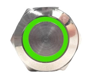
The Self-Locking Push Button with LED (Manufacturer: Generic, Part ID: 001) is a versatile electronic component that combines a push button switch with a locking mechanism and an integrated LED indicator. When pressed, the button locks into place, maintaining its state until pressed again to release. The LED provides a visual indication of the button's status, making it ideal for applications requiring clear feedback.
Explore Projects Built with Self Locking push button with LED
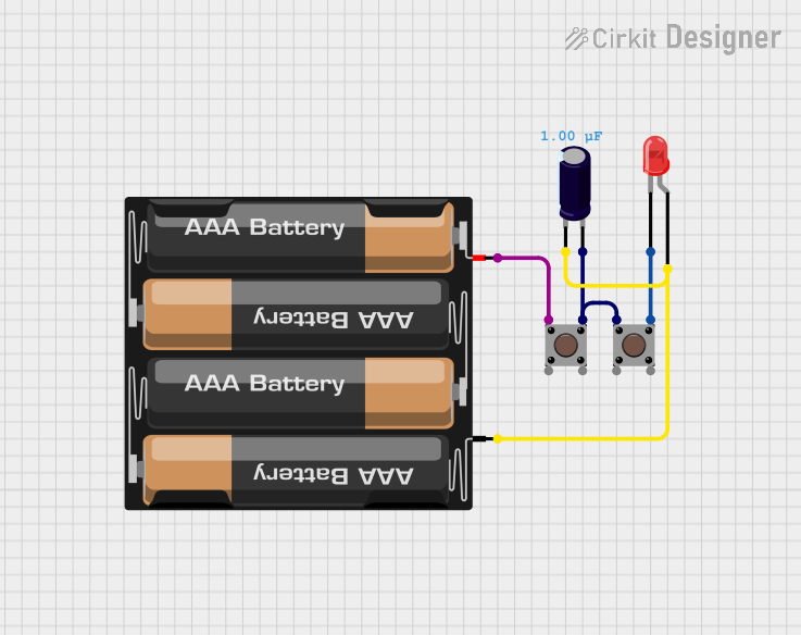
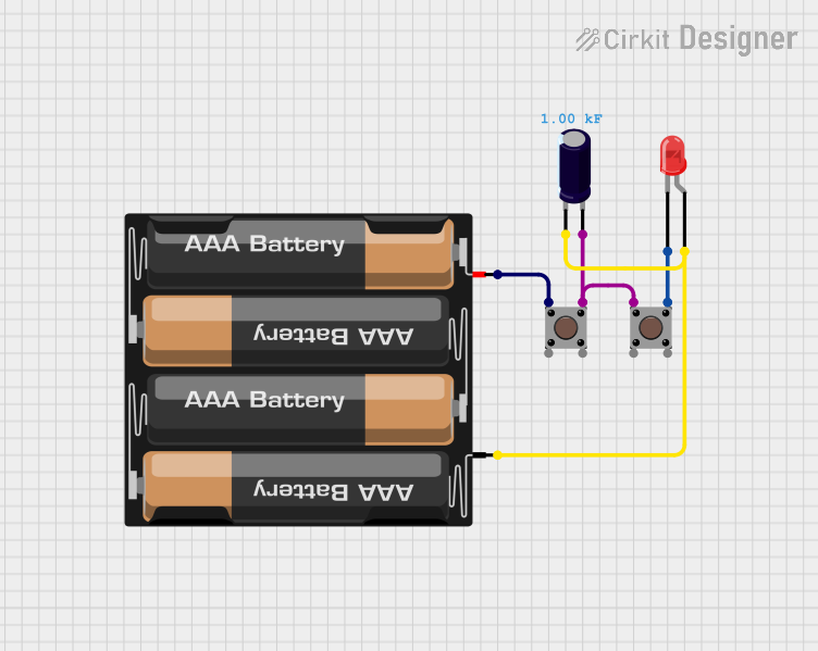
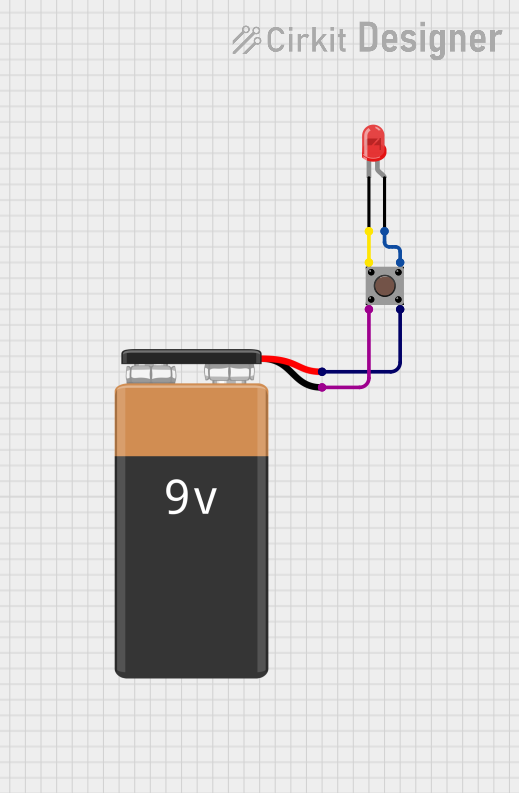
Explore Projects Built with Self Locking push button with LED
Common Applications and Use Cases
- Power switches for electronic devices
- Control panels and dashboards
- DIY electronics and prototyping
- Home automation systems
- Industrial equipment controls
Technical Specifications
Below are the key technical details for the Self-Locking Push Button with LED:
| Parameter | Value |
|---|---|
| Manufacturer | Generic |
| Part ID | 001 |
| Operating Voltage | 3V to 12V DC |
| LED Current | 10mA to 20mA |
| Switch Current Rating | Up to 3A |
| Contact Resistance | ≤ 50mΩ |
| Insulation Resistance | ≥ 100MΩ |
| Mechanical Life | 50,000 cycles |
| Mounting Type | Panel mount |
| Button Type | Self-locking (latching) |
| LED Color | Red (varies by model) |
Pin Configuration and Descriptions
The Self-Locking Push Button with LED typically has four pins. The table below describes each pin:
| Pin | Label | Description |
|---|---|---|
| 1 | NC | Normally Closed terminal for the switch. Connected when the button is released. |
| 2 | NO | Normally Open terminal for the switch. Connected when the button is pressed. |
| 3 | COM | Common terminal for the switch. |
| 4 | LED+ | Positive terminal for the LED. |
| 5 | LED- | Negative terminal for the LED. |
Note: Some models may combine the LED- pin with the COM pin. Always refer to the specific datasheet for your model.
Usage Instructions
How to Use the Component in a Circuit
Wiring the Switch:
- Connect the COM pin to the input voltage or signal source.
- Use the NO pin to connect to the load or circuit that should be activated when the button is pressed.
- Optionally, connect the NC pin if you need a normally closed configuration.
Wiring the LED:
- Connect the LED+ pin to the positive voltage supply (e.g., 5V).
- Connect the LED- pin to ground through a current-limiting resistor (typically 220Ω to 1kΩ, depending on the supply voltage).
Powering the Circuit:
- Ensure the operating voltage is within the specified range (3V to 12V DC).
- Verify that the current through the LED does not exceed 20mA.
Important Considerations and Best Practices
- Current Limiting for LED: Always use a resistor in series with the LED to prevent damage due to excessive current.
- Debouncing: Mechanical switches like this one may produce noise or "bouncing" when pressed. Use a capacitor or software debouncing techniques in microcontroller applications.
- Voltage Compatibility: Ensure the LED voltage matches your circuit's supply voltage. If necessary, use a resistor to adjust the voltage.
- Mounting: Securely mount the button on a panel to prevent accidental disconnection or damage.
Example: Connecting to an Arduino UNO
Below is an example of how to connect and use the Self-Locking Push Button with LED with an Arduino UNO:
Circuit Connections
- COM pin → Arduino digital pin 2 (configured as input).
- NO pin → Ground.
- LED+ pin → Arduino 5V.
- LED- pin → Ground through a 220Ω resistor.
Arduino Code
// Self-Locking Push Button with LED Example
// This code reads the button state and toggles the LED accordingly.

const int buttonPin = 2;  // Pin connected to the COM pin of the button
const int ledPin = 13;    // Built-in LED on Arduino (for demonstration)

void setup() {
  pinMode(buttonPin, INPUT_PULLUP); // Set button pin as input with pull-up resistor
  pinMode(ledPin, OUTPUT);         // Set LED pin as output
}

void loop() {
  // Read the button state (LOW when pressed, HIGH when released)
  int buttonState = digitalRead(buttonPin);

  // Toggle the LED based on the button state
  if (buttonState == LOW) {
    digitalWrite(ledPin, HIGH); // Turn on the LED
  } else {
    digitalWrite(ledPin, LOW);  // Turn off the LED
  }
}
Note: The example assumes the button is connected in a pull-up configuration. Adjust the wiring and code as needed for your specific setup.
Troubleshooting and FAQs
Common Issues and Solutions
LED Does Not Light Up:
- Check the polarity of the LED connections (LED+ and LED-).
- Verify the current-limiting resistor value and ensure it is not too high.
- Ensure the supply voltage is within the operating range (3V to 12V DC).
Button Does Not Lock in Place:
- Inspect the mechanical locking mechanism for damage or debris.
- Ensure the button is securely mounted and not obstructed.
Switch Does Not Work:
- Verify the wiring of the COM, NO, and NC pins.
- Check for loose connections or damaged wires.
Button Bounces or Produces Erratic Behavior:
- Use a capacitor (e.g., 0.1µF) across the switch terminals to reduce noise.
- Implement software debouncing in your microcontroller code.
FAQs
Q: Can I use this button with a 3.3V microcontroller?
A: Yes, the button and LED can operate at 3.3V. Ensure the current-limiting resistor for the LED is adjusted accordingly.
Q: Is the LED color customizable?
A: The default LED color is red, but some models may offer other colors. Check with your supplier for availability.
Q: Can I use this button for AC circuits?
A: This button is designed for low-voltage DC circuits. Using it with AC circuits may damage the component or pose safety risks.
Q: How do I clean the button if it gets stuck?
A: Use compressed air or a small brush to remove debris. Avoid using liquids that may damage the internal mechanism.
By following this documentation, you can effectively integrate the Self-Locking Push Button with LED into your projects and troubleshoot common issues with ease.