How to Use 8-Channel 5v Relay Shield: Examples, Pinouts, and Specs
Introduction
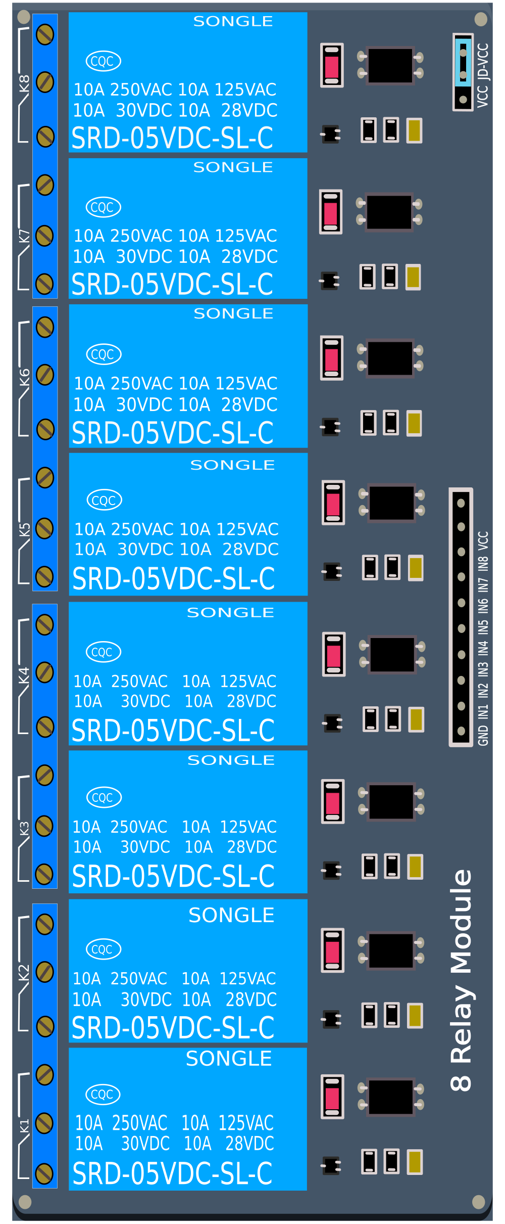
The 8-Channel 5V Relay Shield is an electronic device designed to interface with microcontrollers like the Arduino UNO, allowing for the control of up to eight separate high-power devices. This shield is ideal for applications in home automation, industrial controls, and other scenarios where electrical isolation between a low voltage control circuit and a high voltage or high current load is required.
Explore Projects Built with 8-Channel 5v Relay Shield


Explore Projects Built with 8-Channel 5v Relay Shield
Common Applications and Use Cases
- Home automation systems
- Industrial machine control
- Remote power switch
- Automotive electronics
- Hobbyist electronic projects
Technical Specifications
Key Technical Details
- Operating Voltage: 5V
- Relay Maximum Output:
- DC 30V/10A
- AC 250V/10A
- Control Signal: TTL level
- Current Consumption: 15-20mA per relay
- Relay Life: 100,000 cycles
Pin Configuration and Descriptions
| Pin Number | Description | Type |
|---|---|---|
| IN1 | Control signal for Relay 1 | Digital |
| IN2 | Control signal for Relay 2 | Digital |
| IN3 | Control signal for Relay 3 | Digital |
| IN4 | Control signal for Relay 4 | Digital |
| IN5 | Control signal for Relay 5 | Digital |
| IN6 | Control signal for Relay 6 | Digital |
| IN7 | Control signal for Relay 7 | Digital |
| IN8 | Control signal for Relay 8 | Digital |
| GND | Ground | Power |
| VCC | 5V Supply | Power |
| JD-VCC | Relay Power Jumper | Power |
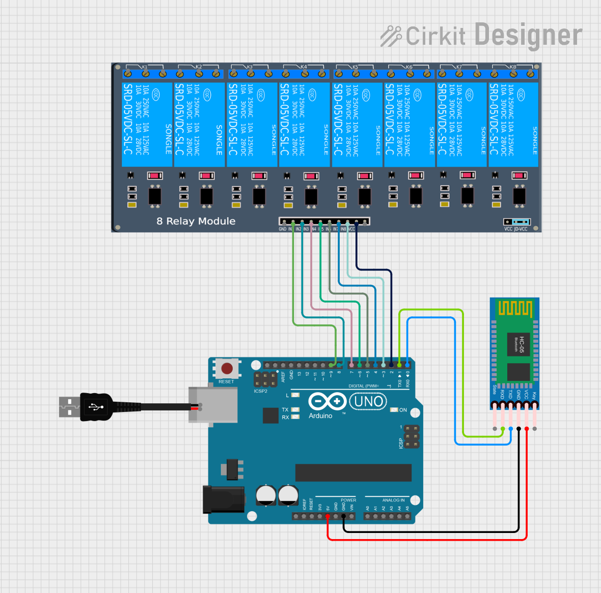
Usage Instructions
How to Use the Component in a Circuit
- Connect the VCC pin to the 5V output on the Arduino.
- Connect the GND pin to the ground on the Arduino.
- Connect the IN1-IN8 pins to the digital outputs on the Arduino.
- Ensure that the JD-VCC jumper is in place if you are using the same power supply for the relays and the input logic.
- Connect the high-power circuit to the relay terminals, ensuring proper isolation and safety precautions.
Important Considerations and Best Practices
- Always ensure the power ratings of the relay are not exceeded by the connected load.
- Use flyback diodes when controlling inductive loads to prevent back EMF damage.
- Ensure proper isolation between the low voltage control side and high voltage load side.
- Consider using snubber circuits for highly inductive or noisy loads to protect the relay contacts.
- Avoid placing the relay shield in environments with high humidity or dust to prevent short circuits.
Example Code for Arduino UNO
// Example code to control an 8-Channel 5V Relay Shield with an Arduino UNO

void setup() {
  // Initialize all the relay control pins as OUTPUT
  for (int i = 2; i <= 9; i++) {
    pinMode(i, OUTPUT);
  }
}

void loop() {
  // Turn on each relay one after the other with a 1-second delay
  for (int i = 2; i <= 9; i++) {
    digitalWrite(i, HIGH); // Turn on relay
    delay(1000);           // Wait for 1 second
    digitalWrite(i, LOW);  // Turn off relay
    delay(1000);           // Wait for 1 second
  }
}
Troubleshooting and FAQs
Common Issues Users Might Face
- Relay not activating: Check the control signal and power connections. Ensure the input signal is at TTL level.
- Intermittent operation: Verify that there is no loose connection and that the power supply is stable and sufficient.
- Noise issues: In cases where the relay is switching an inductive load, ensure a flyback diode is used.
Solutions and Tips for Troubleshooting
- Double-check wiring, especially the ground connection between the Arduino and the relay shield.
- Use a separate power supply for the relays if the Arduino cannot provide sufficient current.
- If using a separate power supply, remove the JD-VCC jumper and connect the external supply to the JD-VCC pin.
FAQs
Q: Can I control the relays with a 3.3V signal? A: The relays are designed for 5V TTL signals. A 3.3V signal may not reliably activate the relay.
Q: How many relays can I activate at once? A: You can activate all eight relays simultaneously, provided the power supply can handle the current draw.
Q: Can I use this shield with other microcontrollers besides Arduino? A: Yes, any microcontroller with compatible 5V digital outputs can control this relay shield.