How to Use Relay điện: Examples, Pinouts, and Specs
Introduction
A relay is an electromechanical switch that uses an electromagnetic coil to open or close a circuit, allowing control of high-power devices with low-power signals. Relays are widely used in applications where electrical isolation, high-current switching, or remote control of circuits is required. They are essential in automation systems, home appliances, automotive electronics, and industrial equipment.
Explore Projects Built with Relay điện
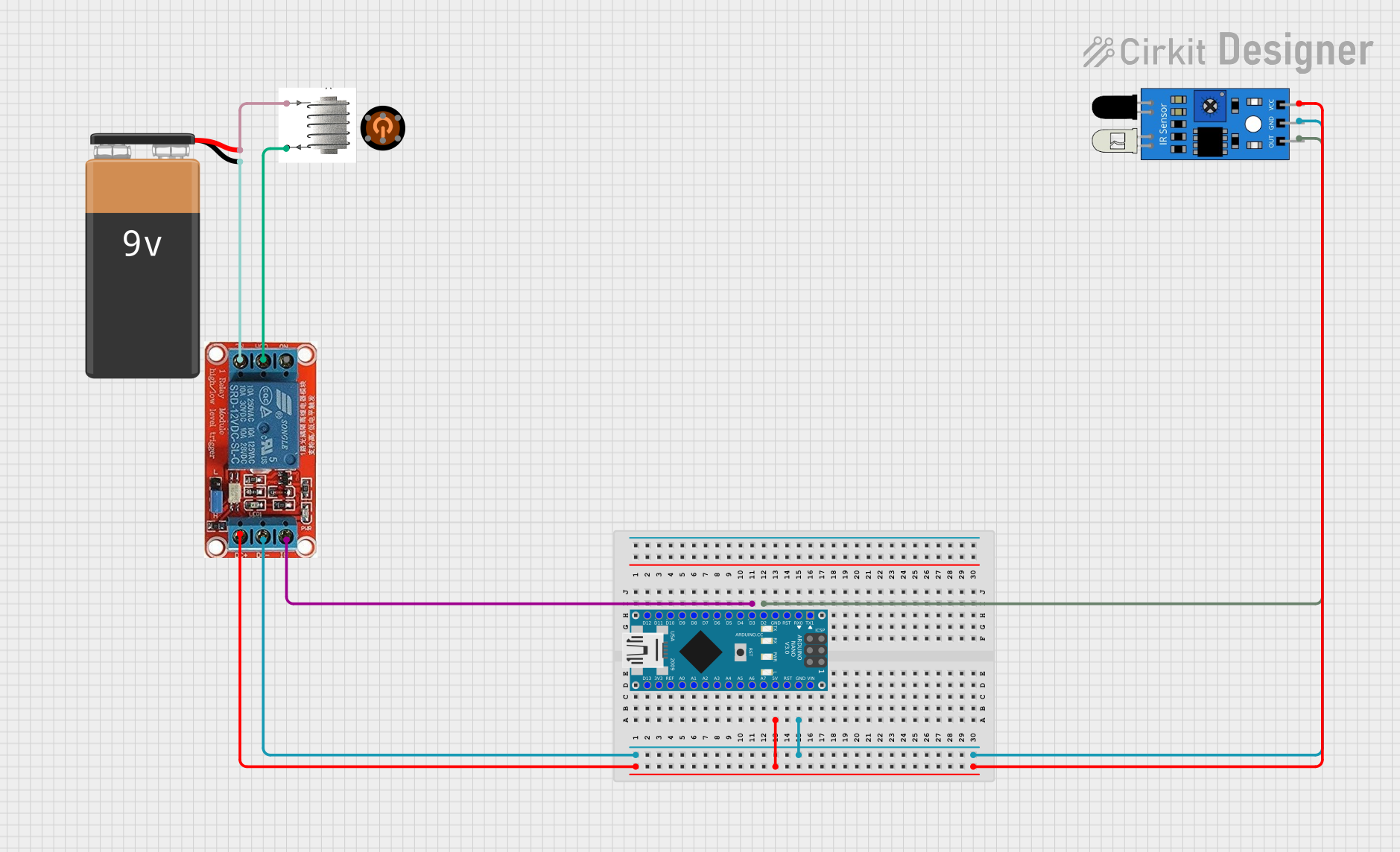
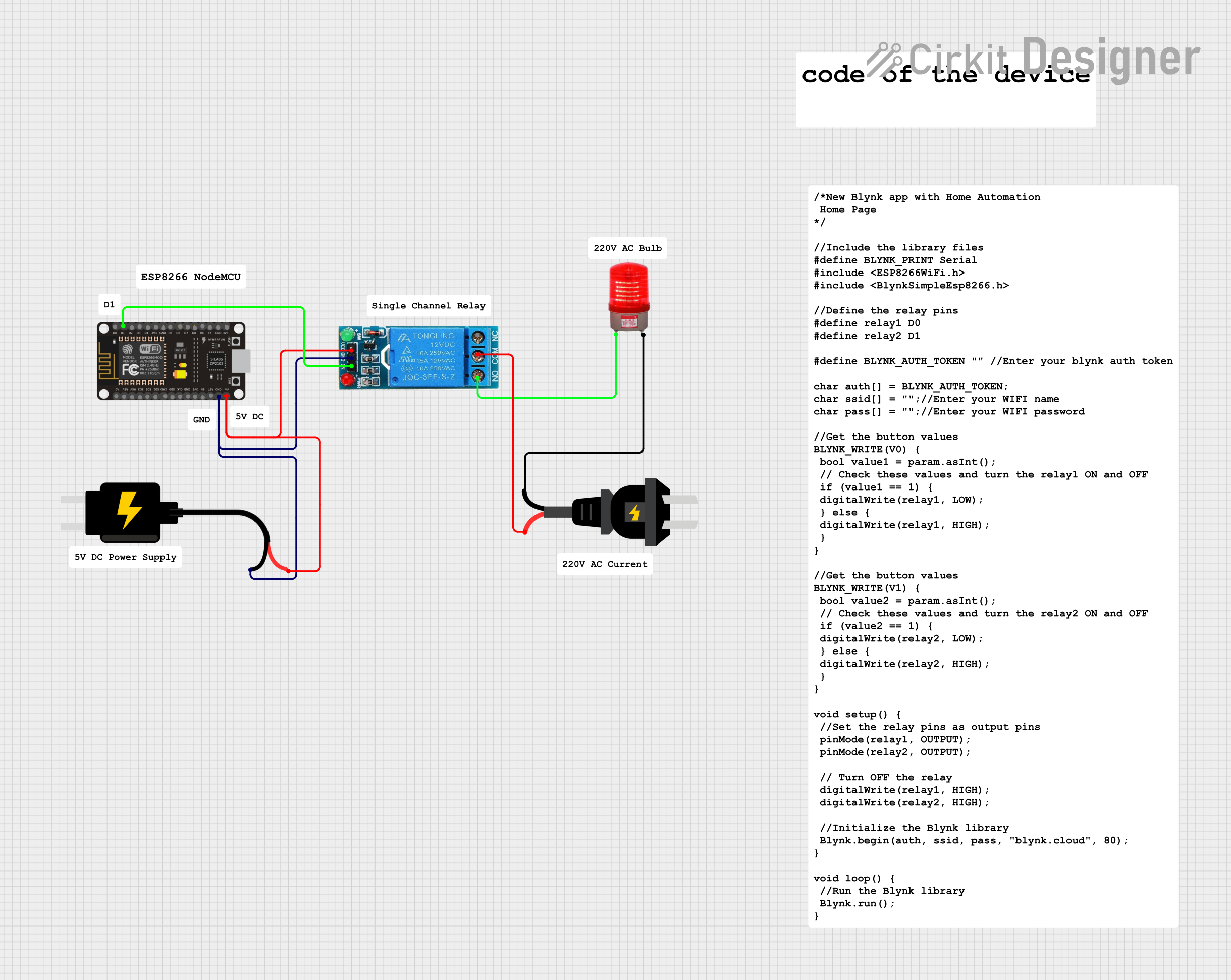
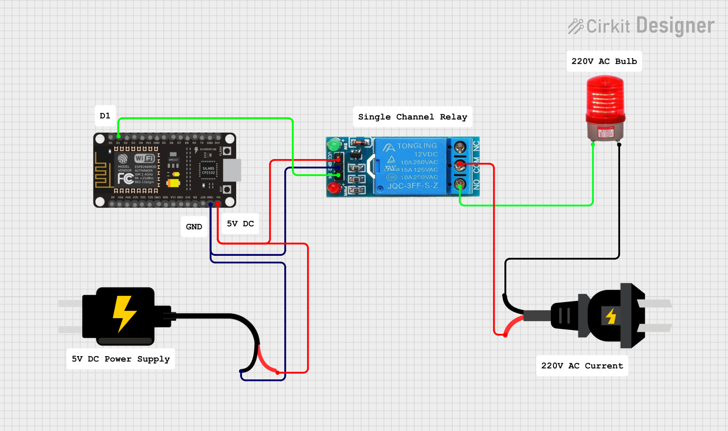
Explore Projects Built with Relay điện
Common Applications:
- Home automation (e.g., controlling lights or appliances)
- Automotive systems (e.g., controlling headlights or horns)
- Industrial control systems
- Microcontroller-based projects (e.g., Arduino or Raspberry Pi)
- Power distribution and protection circuits
Technical Specifications
Key Technical Details:
- Coil Voltage: Typically 5V, 12V, or 24V DC (depending on the relay model)
- Switching Voltage: Up to 250V AC or 30V DC
- Switching Current: Up to 10A (varies by model)
- Contact Configuration: SPDT (Single Pole Double Throw) or DPDT (Double Pole Double Throw)
- Coil Resistance: Varies based on the relay's coil voltage
- Isolation: Electrical isolation between the control circuit and the load circuit
- Lifetime: Mechanical (millions of operations) and electrical (hundreds of thousands of operations)
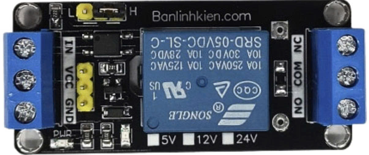
Pin Configuration and Descriptions:
Below is the pin configuration for a typical 5V SPDT relay module:
| Pin Name | Description |
|---|---|
| VCC | Connects to the positive supply voltage (e.g., 5V DC). |
| GND | Connects to the ground of the power supply. |
| IN | Control signal input (e.g., from a microcontroller like Arduino). |
| COM | Common terminal for the relay switch. |
| NO | Normally Open terminal. Connects to COM when the relay is activated. |
| NC | Normally Closed terminal. Connects to COM when the relay is not activated. |
Usage Instructions
How to Use the Relay in a Circuit:
- Power the Relay Module: Connect the VCC and GND pins to a 5V DC power supply.
- Control Signal: Connect the IN pin to a digital output pin of a microcontroller (e.g., Arduino).
- Load Connection:
- Connect the device or circuit you want to control to the NO (Normally Open) terminal.
- Connect the other side of the load to the power source.
- The COM terminal should be connected to the other side of the power source.
- Activate the Relay: Send a HIGH signal (e.g., 5V) to the IN pin to activate the relay and close the circuit between COM and NO.
Important Considerations:
- Flyback Diode: Ensure the relay module has a built-in flyback diode to protect the circuit from voltage spikes caused by the relay coil.
- Power Ratings: Do not exceed the relay's voltage and current ratings to avoid damage.
- Isolation: Use optocouplers or isolation circuits if the relay is controlling high-voltage loads.
- Debouncing: If switching rapidly, consider debouncing techniques to avoid erratic behavior.
Example Code for Arduino UNO:
// This example demonstrates how to control a relay module with an Arduino UNO.
// The relay is connected to pin 7 of the Arduino.

#define RELAY_PIN 7  // Define the pin connected to the relay module

void setup() {
  pinMode(RELAY_PIN, OUTPUT);  // Set the relay pin as an output
  digitalWrite(RELAY_PIN, LOW);  // Ensure the relay is off at startup
}

void loop() {
  digitalWrite(RELAY_PIN, HIGH);  // Turn the relay on
  delay(1000);  // Keep the relay on for 1 second
  digitalWrite(RELAY_PIN, LOW);  // Turn the relay off
  delay(1000);  // Keep the relay off for 1 second
}
Notes:
- Replace
RELAY_PINwith the appropriate pin number if using a different setup. - Ensure the relay module's power supply matches its rated voltage (e.g., 5V).
Troubleshooting and FAQs
Common Issues:
Relay Not Activating:
- Check if the control signal voltage matches the relay's input requirements.
- Verify the power supply connections (VCC and GND).
- Ensure the microcontroller pin is configured as an output.
Relay Clicking but Load Not Working:
- Confirm the load is properly connected to the NO or NC terminal and COM terminal.
- Check the load's power source and ensure it is functioning.
Voltage Spikes or Noise:
- Use a flyback diode across the relay coil if not already included in the module.
- Add capacitors or snubber circuits to suppress noise.
Relay Overheating:
- Ensure the load does not exceed the relay's current and voltage ratings.
- Use a heatsink or cooling mechanism if necessary.
FAQs:
Can I use a relay with an AC load? Yes, relays are designed to handle both AC and DC loads. Ensure the relay's ratings match the AC voltage and current requirements.
What is the difference between NO and NC terminals?
- NO (Normally Open): The circuit is open when the relay is inactive and closes when activated.
- NC (Normally Closed): The circuit is closed when the relay is inactive and opens when activated.
Can I control multiple relays with one microcontroller? Yes, you can control multiple relays by connecting each relay's IN pin to a separate digital output pin on the microcontroller.
Why is electrical isolation important in relays? Electrical isolation protects the control circuit (e.g., microcontroller) from high voltages or currents in the load circuit, ensuring safety and preventing damage.
By following this documentation, you can effectively use a relay in your electronic projects while ensuring safety and reliability.