How to Use I2C-UART Bi-Directional Logic Level Converter 5V-3.3V 2-channel with supply: Examples, Pinouts, and Specs
Introduction
The TinyTronics I2C-UART Bi-Directional Logic Level Converter (Part ID: 000147) is a compact and efficient device designed to enable seamless communication between two devices operating at different voltage levels, specifically 5V and 3.3V. This converter supports bi-directional signal conversion, making it ideal for interfacing microcontrollers, sensors, and communication modules that operate at varying logic levels. With two independent channels, it allows simultaneous data transfer, and its integrated power supply ensures stable operation.
Explore Projects Built with I2C-UART Bi-Directional Logic Level Converter 5V-3.3V 2-channel with supply


Explore Projects Built with I2C-UART Bi-Directional Logic Level Converter 5V-3.3V 2-channel with supply
Common Applications and Use Cases
- Interfacing 5V microcontrollers (e.g., Arduino) with 3.3V sensors or modules (e.g., I2C or UART devices).
- Enabling communication between 3.3V microcontrollers (e.g., ESP32) and 5V peripherals.
- Level shifting for serial communication protocols like I2C, UART, and SPI.
- Prototyping and development of mixed-voltage systems.
Technical Specifications
Key Technical Details
| Parameter | Value |
|---|---|
| Manufacturer | TinyTronics |
| Part ID | 000147 |
| Voltage Levels Supported | 5V ↔ 3.3V |
| Number of Channels | 2 |
| Communication Protocols | I2C, UART, SPI |
| Power Supply Input Voltage | 5V |
| Operating Temperature | -40°C to +85°C |
| Dimensions | 15mm x 12mm x 3mm |
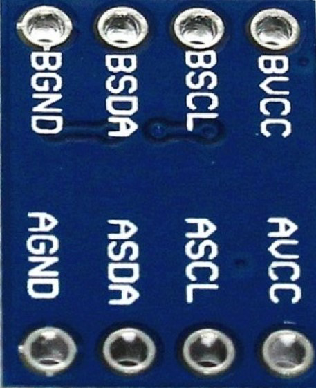
Pin Configuration and Descriptions
| Pin Name | Description |
|---|---|
| HV | High Voltage Input (5V). Connect to the 5V power source. |
| LV | Low Voltage Input (3.3V). Connect to the 3.3V power source. |
| GND | Ground. Common ground for both voltage levels. |
| HV1 | High Voltage Channel 1. Connect to the 5V signal line of the first channel. |
| LV1 | Low Voltage Channel 1. Connect to the 3.3V signal line of the first channel. |
| HV2 | High Voltage Channel 2. Connect to the 5V signal line of the second channel. |
| LV2 | Low Voltage Channel 2. Connect to the 3.3V signal line of the second channel. |
Usage Instructions
How to Use the Component in a Circuit
Power Connections:
- Connect the HV pin to the 5V power source of your system.
- Connect the LV pin to the 3.3V power source of your system.
- Connect the GND pin to the common ground of your circuit.
Signal Connections:
- For the first channel, connect the 5V signal line to HV1 and the corresponding 3.3V signal line to LV1.
- For the second channel, connect the 5V signal line to HV2 and the corresponding 3.3V signal line to LV2.
Communication Protocols:
- The converter supports I2C, UART, and SPI protocols. Ensure proper pull-up resistors are used for I2C communication if required.
Testing:
- Verify the voltage levels on both sides of the converter using a multimeter before connecting sensitive devices.
Important Considerations and Best Practices
- Ensure that the HV and LV power supplies are stable and within the specified voltage range.
- Avoid exceeding the maximum current rating of the converter to prevent damage.
- Use short and properly shielded wires for high-speed communication to minimize noise.
- For I2C communication, ensure that the pull-up resistors are correctly placed on the appropriate voltage side (5V or 3.3V).
Example: Connecting to an Arduino UNO
Below is an example of using the logic level converter to interface an Arduino UNO (5V) with a 3.3V I2C sensor.
Circuit Connections
- HV → Arduino 5V
- LV → Sensor 3.3V
- GND → Common ground
- HV1 → Arduino SDA (A4)
- LV1 → Sensor SDA
- HV2 → Arduino SCL (A5)
- LV2 → Sensor SCL
Arduino Code Example
#include <Wire.h> // Include the Wire library for I2C communication

void setup() {
  Wire.begin(); // Initialize I2C communication
  Serial.begin(9600); // Start serial communication for debugging

  // Example: Sending a request to a 3.3V I2C sensor with address 0x40
  Serial.println("Initializing communication with 3.3V sensor...");
  Wire.beginTransmission(0x40); // Start communication with sensor
  Wire.write(0x00); // Send a command or register address
  Wire.endTransmission(); // End transmission
}

void loop() {
  // Example: Reading data from the sensor
  Wire.requestFrom(0x40, 2); // Request 2 bytes from the sensor
  if (Wire.available() == 2) { // Check if 2 bytes are available
    int data = Wire.read() << 8 | Wire.read(); // Combine the two bytes
    Serial.print("Sensor Data: ");
    Serial.println(data); // Print the received data
  }
  delay(1000); // Wait 1 second before the next read
}
Troubleshooting and FAQs
Common Issues and Solutions
No Signal Conversion:
- Cause: Incorrect power supply connections.
- Solution: Verify that the HV and LV pins are connected to the correct voltage sources.
Communication Errors:
- Cause: Missing or incorrect pull-up resistors for I2C communication.
- Solution: Add appropriate pull-up resistors (e.g., 4.7kΩ) to the SDA and SCL lines.
Voltage Mismatch:
- Cause: Incorrect signal connections or damaged converter.
- Solution: Double-check the wiring and measure the voltage levels on both sides.
Overheating:
- Cause: Exceeding the current rating of the converter.
- Solution: Reduce the load or use a higher-rated converter.
FAQs
Q1: Can this converter handle SPI communication?
Yes, the converter supports SPI communication. Ensure proper wiring of the MOSI, MISO, and SCK lines to the appropriate channels.
Q2: Can I use this converter for 1.8V devices?
No, this converter is specifically designed for 5V ↔ 3.3V level shifting. For 1.8V devices, use a dedicated 1.8V level shifter.
Q3: Do I need external pull-up resistors for UART communication?
No, UART communication typically does not require pull-up resistors. However, ensure proper wiring and voltage levels.
Q4: Can I use both channels simultaneously?
Yes, the two channels are independent and can be used simultaneously for different signals.