How to Use FRDM-MCNX947: Examples, Pinouts, and Specs
Introduction
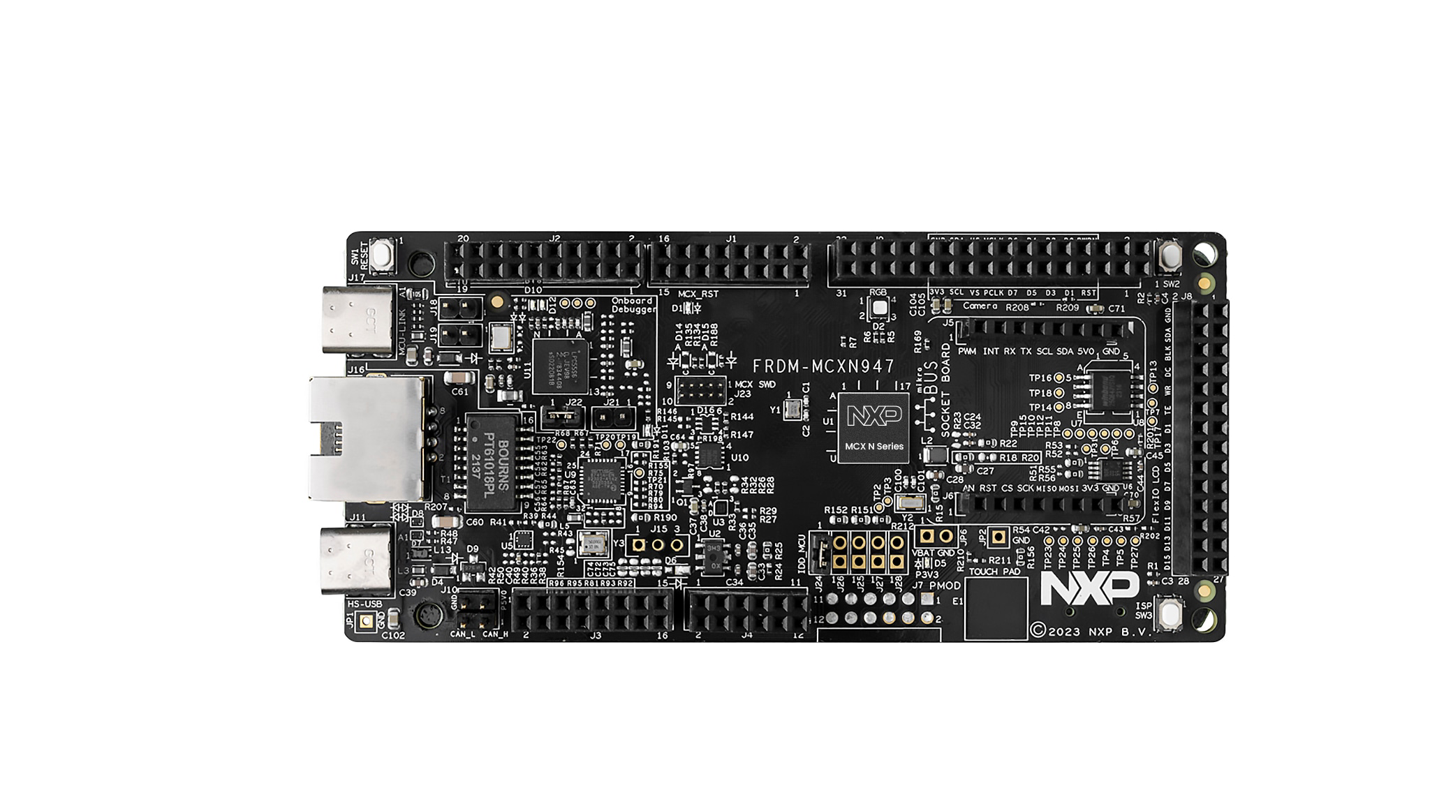
The FRDM-MCNX947 is a development platform manufactured by NXP. It is designed to facilitate rapid prototyping and development of applications using the NXP Kinetis MCUs. This board is powered by the MCUXpresso SDK, which provides a comprehensive software development environment. The FRDM-MCNX947 includes a variety of onboard interfaces, sensors, and connectivity options, making it an excellent choice for IoT, embedded systems, and industrial automation projects.
Explore Projects Built with FRDM-MCNX947


Explore Projects Built with FRDM-MCNX947
Common Applications
- Internet of Things (IoT) devices
- Industrial control systems
- Wearable technology
- Home automation
- Prototyping and educational purposes
Technical Specifications
Key Technical Details
| Specification | Value/Description |
|---|---|
| Microcontroller | NXP Kinetis MCU (ARM Cortex-M4 core) |
| Operating Voltage | 3.3V |
| Input Voltage Range | 5V (via USB) or 7-12V (via external power supply) |
| Clock Speed | Up to 120 MHz |
| Flash Memory | 512 KB |
| RAM | 128 KB |
| Communication Interfaces | UART, SPI, I2C, CAN, USB |
| Onboard Sensors | Accelerometer, Magnetometer, Temperature Sensor |
| Debugging Interface | OpenSDA (USB-based debug interface) |
| GPIO Pins | 40+ (multipurpose, configurable) |
| Dimensions | 90 mm x 60 mm |
Pin Configuration and Descriptions
The FRDM-MCNX947 features a variety of pins for interfacing with external components. Below is a summary of the key pin configurations:
GPIO and Power Pins
| Pin Name | Description | Voltage Level |
|---|---|---|
| 3.3V | Power output for external components | 3.3V |
| 5V | Power output for external components | 5V |
| GND | Ground | 0V |
| GPIO0-GPIO39 | General-purpose input/output pins | 3.3V |
Communication Pins
| Pin Name | Description | Voltage Level |
|---|---|---|
| UART_TX | UART Transmit | 3.3V |
| UART_RX | UART Receive | 3.3V |
| SPI_MOSI | SPI Master Out, Slave In | 3.3V |
| SPI_MISO | SPI Master In, Slave Out | 3.3V |
| SPI_SCK | SPI Clock | 3.3V |
| I2C_SDA | I2C Data | 3.3V |
| I2C_SCL | I2C Clock | 3.3V |
| CAN_H | CAN High | 3.3V |
| CAN_L | CAN Low | 3.3V |
Usage Instructions
How to Use the FRDM-MCNX947 in a Circuit
Powering the Board:
- Connect the board to your computer via the USB port for power and programming.
- Alternatively, use an external power supply (7-12V) connected to the power input jack.
Programming the Board:
- Install the MCUXpresso IDE and SDK from the NXP website.
- Use the OpenSDA interface to program the board via USB.
- Load your application code onto the board using the drag-and-drop programming feature.
Connecting Peripherals:
- Use the GPIO pins to connect external sensors, actuators, or other devices.
- For communication, use the UART, SPI, or I2C pins as required by your application.
Debugging:
- Use the OpenSDA interface for real-time debugging and monitoring.
- The MCUXpresso IDE provides tools for setting breakpoints, inspecting variables, and more.
Important Considerations and Best Practices
- Ensure that the input voltage does not exceed the specified range to avoid damaging the board.
- Use level shifters if interfacing with components that operate at voltages higher than 3.3V.
- Avoid connecting high-current loads directly to the GPIO pins; use external drivers or relays.
- Always check the pin configuration and ensure proper connections to avoid short circuits.
Example: Using the FRDM-MCNX947 with Arduino UNO
The FRDM-MCNX947 can communicate with an Arduino UNO via UART. Below is an example of how to send data from the FRDM-MCNX947 to the Arduino UNO:
FRDM-MCNX947 Code (MCUXpresso IDE)
#include "fsl_uart.h"  // Include UART driver from MCUXpresso SDK

#define UART_BASEADDR UART0  // Define UART base address
#define UART_CLK_FREQ CLOCK_GetFreq(UART0_CLK_SRC)  // Get UART clock frequency

void UART_Init(void) {
    uart_config_t config;
    UART_GetDefaultConfig(&config);  // Load default UART configuration
    config.baudRate_Bps = 9600;      // Set baud rate to 9600
    config.enableTx = true;          // Enable UART transmission
    config.enableRx = false;         // Disable UART reception
    UART_Init(UART_BASEADDR, &config, UART_CLK_FREQ);  // Initialize UART
}

void UART_SendString(const char *str) {
    while (*str) {
        UART_WriteBlocking(UART_BASEADDR, (uint8_t *)str, 1);  // Send one char
        str++;  // Move to the next character
    }
}

int main(void) {
    BOARD_InitBootPins();  // Initialize board pins
    BOARD_InitBootClocks();  // Initialize board clocks
    UART_Init();  // Initialize UART

    while (1) {
        UART_SendString("Hello, Arduino!\r\n");  // Send message to Arduino
        for (volatile int i = 0; i < 1000000; i++) {
            __NOP();  // Delay loop
        }
    }
}
Arduino UNO Code
void setup() {
    Serial.begin(9600);  // Initialize serial communication at 9600 baud
}

void loop() {
    if (Serial.available()) {  // Check if data is available
        String message = Serial.readString();  // Read the incoming message
        Serial.println("Received: " + message);  // Print the received message
    }
}
Troubleshooting and FAQs
Common Issues and Solutions
Board Not Detected by Computer:
- Ensure the USB cable is properly connected and functional.
- Check if the OpenSDA firmware is up to date.
Program Not Running After Upload:
- Verify that the correct MCU target is selected in the MCUXpresso IDE.
- Ensure the board is powered and not in reset mode.
Communication Issues with Peripherals:
- Double-check the pin connections and configurations.
- Ensure the peripheral device operates at 3.3V or use a level shifter.
Debugging Not Working:
- Confirm that the OpenSDA driver is installed on your computer.
- Restart the MCUXpresso IDE and reconnect the board.
FAQs
Q: Can I use the FRDM-MCNX947 for battery-powered applications?
A: Yes, the board can be powered using a battery pack connected to the external power input. Ensure the voltage is within the 7-12V range.
Q: Is the FRDM-MCNX947 compatible with other IDEs?
A: While the MCUXpresso IDE is recommended, the board can also be used with other ARM-compatible IDEs like Keil or IAR.
Q: How do I update the OpenSDA firmware?
A: Visit the NXP website, download the latest firmware, and follow the provided instructions to update the OpenSDA interface.