
How to Use DSPIC30F4011: Examples, Pinouts, and Specs
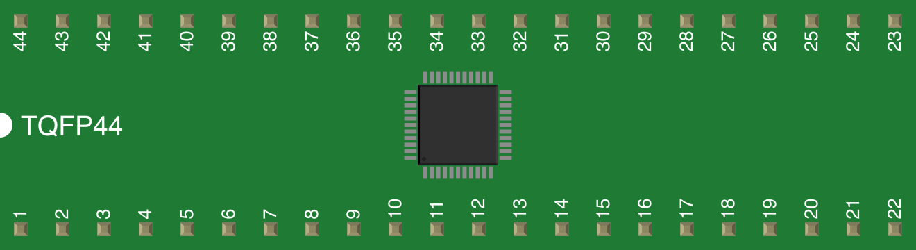
 Design with DSPIC30F4011 in Cirkit Designer
Introduction
The dsPIC30F4011 is a 16-bit Digital Signal Controller (DSC) manufactured by Microchip Technology. It combines the performance of a Digital Signal Processor (DSP) with the simplicity of a microcontroller, making it ideal for high-performance embedded applications. With a processing speed of up to 30 MIPS (Million Instructions Per Second), integrated DSP capabilities, and multiple communication interfaces, the dsPIC30F4011 is well-suited for applications requiring real-time control, signal processing, and efficient computation.
Explore Projects Built with DSPIC30F4011
 Open Project in Cirkit Designer
 Open Project in Cirkit Designer
 Open Project in Cirkit Designer
 Open Project in Cirkit Designer
Explore Projects Built with DSPIC30F4011
Open Project in Cirkit DesignerOpen Project in Cirkit DesignerOpen Project in Cirkit DesignerOpen Project in Cirkit DesignerCommon Applications
- Motor control systems (e.g., BLDC, PMSM, and AC induction motors)
- Power inverters and converters
- Audio signal processing
- Industrial automation and control
- Sensor interfacing and data acquisition
- Embedded systems requiring real-time DSP functionality
Technical Specifications
Key Technical Details
| Parameter | Value |
|---|---|
| Core Architecture | 16-bit Digital Signal Controller (DSC) |
| Maximum Clock Speed | 30 MIPS |
| Program Memory (Flash) | 48 KB |
| Data Memory (RAM) | 2 KB |
| Operating Voltage Range | 2.5V to 5.5V |
| I/O Pins | 30 |
| Communication Interfaces | UART, SPI, I²C, CAN |
| Timers | 5 (16-bit timers) |
| ADC Resolution | 10-bit, up to 16 channels |
| PWM Outputs | 6 PWM channels |
| Package Options | 40-pin PDIP, 44-pin TQFP, 44-pin QFN |
Pin Configuration and Descriptions
The dsPIC30F4011 is available in multiple package types. Below is the pin configuration for the 40-pin PDIP package:
| Pin No. | Pin Name | Description |
|---|---|---|
| 1 | VDD | Positive supply voltage |
| 2 | VSS | Ground |
| 3 | OSC1/CLKI | Oscillator input or external clock input |
| 4 | OSC2/CLKO | Oscillator output or clock output |
| 5 | MCLR | Master Clear (Reset) input |
| 6-13 | RA0-RA7 | General-purpose I/O pins |
| 14-21 | RB0-RB7 | General-purpose I/O pins |
| 22 | VCAP | Voltage regulator capacitor connection |
| 23-30 | RC0-RC7 | General-purpose I/O pins |
| 31-38 | RD0-RD7 | General-purpose I/O pins |
| 39 | AVDD | Analog supply voltage |
| 40 | AVSS | Analog ground |
Note: Pin functions may vary depending on the configuration of peripherals and alternate pin functions.
Usage Instructions
How to Use the dsPIC30F4011 in a Circuit
Power Supply:
- Ensure the operating voltage is within the range of 2.5V to 5.5V.
- Connect the VDD and VSS pins to the power supply and ground, respectively.
- Use a decoupling capacitor (e.g., 0.1 µF) close to the VDD pin to reduce noise.
Clock Configuration:
- Connect an external crystal oscillator to the OSC1 and OSC2 pins for precise timing.
- Alternatively, use an external clock source on the OSC1 pin.
Reset Circuit:
- Connect the MCLR pin to a pull-up resistor (e.g., 10 kΩ) to VDD for proper reset functionality.
- Optionally, add a push-button switch to manually reset the device.
Peripheral Configuration:
- Configure the I/O pins as digital or analog using the TRIS and ADCON registers.
- Enable communication interfaces (UART, SPI, I²C, or CAN) as needed for your application.
Programming:
- Use a compatible programmer/debugger (e.g., Microchip's MPLAB ICD 4 or PICkit 4) to program the dsPIC30F4011.
- Write and compile your code using Microchip's MPLAB X IDE and XC16 compiler.
Example: Interfacing dsPIC30F4011 with an Arduino UNO
Below is an example of using UART communication between the dsPIC30F4011 and an Arduino UNO:
dsPIC30F4011 UART Configuration Code
#include <xc.h>

// Configuration bits
#pragma config FOSC = XT_PLL8    // XT oscillator with 8x PLL
#pragma config FWDT = OFF        // Watchdog Timer disabled
#pragma config BOR = ON          // Brown-out Reset enabled

void UART_Init(void) {
    U1MODE = 0x8000;  // Enable UART1 module
    U1BRG = 25;       // Baud rate = 9600 (assuming Fosc = 8 MHz)
    U1STA = 0x0400;   // Enable UART1 transmit
}

void UART_Write(char data) {
    while (U1STAbits.UTXBF);  // Wait until the transmit buffer is empty
    U1TXREG = data;           // Transmit data
}

int main(void) {
    UART_Init();  // Initialize UART1

    while (1) {
        UART_Write('H');  // Send 'H' over UART
        __delay_ms(1000); // 1-second delay
    }

    return 0;
}
Arduino UNO Code
void setup() {
    Serial.begin(9600);  // Initialize UART at 9600 baud
}

void loop() {
    if (Serial.available()) {
        char received = Serial.read();  // Read data from UART
        Serial.print("Received: ");     // Print received data
        Serial.println(received);
    }
}
Important Considerations
- Ensure proper decoupling and bypass capacitors are used to minimize noise.
- Avoid exceeding the maximum voltage and current ratings to prevent damage.
- Use appropriate pull-up or pull-down resistors for unused pins to avoid floating states.
- Configure the ADC module carefully to ensure accurate analog-to-digital conversions.
Troubleshooting and FAQs
Common Issues and Solutions
Device Not Responding:
- Verify the power supply connections and ensure the voltage is within the specified range.
- Check the MCLR pin configuration and ensure it is not floating.
UART Communication Fails:
- Ensure the baud rate settings match between the dsPIC30F4011 and the connected device.
- Check the TX and RX pin connections for proper wiring.
Incorrect ADC Readings:
- Verify the analog input voltage is within the ADC reference voltage range.
- Ensure proper configuration of the ADCON registers.
Programming Errors:
- Confirm the programmer/debugger is properly connected to the ICSP pins.
- Check for any errors in the MPLAB X IDE output window during programming.
FAQs
Q: Can the dsPIC30F4011 operate without an external oscillator?
A: Yes, the dsPIC30F4011 has an internal oscillator, but using an external crystal oscillator is recommended for applications requiring precise timing.
Q: How many PWM channels are available?
A: The dsPIC30F4011 provides up to 6 PWM channels, which are ideal for motor control and power management applications.
Q: Is the dsPIC30F4011 suitable for low-power applications?
A: While the dsPIC30F4011 is not specifically designed for ultra-low-power applications, it supports power-saving modes such as Idle and Sleep.
Q: Can I use the dsPIC30F4011 for audio signal processing?
A: Yes, the integrated DSP capabilities make it suitable for audio signal processing tasks such as filtering and FFT.