How to Use Circuit: Examples, Pinouts, and Specs
Introduction
A circuit is a closed path that allows electric current to flow, typically consisting of various components such as resistors, capacitors, inductors, diodes, transistors, and power sources. Circuits are the foundation of all electronic devices and systems, enabling the control, processing, and transmission of electrical signals.
Common applications of circuits include:
- Power distribution in electronic devices
- Signal processing in communication systems
- Control systems in automation and robotics
- Data processing in computers and microcontrollers
- Lighting and energy management systems
Explore Projects Built with Circuit


Explore Projects Built with Circuit
Technical Specifications
Circuits can vary widely in complexity and design, but the following are general technical considerations for basic circuits:
Key Parameters
| Parameter | Description |
|---|---|
| Voltage Range | The operating voltage of the circuit, typically between 3.3V and 24V DC. |
| Current Capacity | The maximum current the circuit can handle, depending on the components. |
| Power Rating | The total power consumption, calculated as Voltage × Current (Watts). |
| Frequency Range | For AC circuits, the frequency range (e.g., 50Hz to 60Hz for mains power). |
| Impedance | The total opposition to current flow, including resistance and reactance. |
Example Pin Configuration (for a simple circuit with a power source and load)
| Pin Name | Description |
|---|---|
| V+ (Positive) | The positive terminal of the power source, supplying voltage to the circuit. |
| GND (Ground) | The ground terminal, completing the circuit and providing a reference point. |
| Load | The component or device consuming power (e.g., LED, motor, resistor). |
Usage Instructions
To use a circuit effectively, follow these steps:
Design the Circuit:
- Identify the purpose of the circuit (e.g., lighting, signal processing).
- Select appropriate components (e.g., resistors, capacitors, transistors) based on the required specifications.
- Create a schematic diagram to visualize the connections.
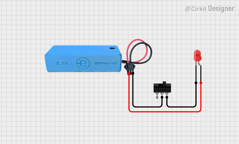
Assemble the Circuit:
- Use a breadboard for prototyping or a PCB for permanent assembly.
- Connect components according to the schematic, ensuring proper orientation for polarized components (e.g., diodes, electrolytic capacitors).
Power the Circuit:
- Connect the power source (e.g., battery, DC adapter) to the circuit.
- Ensure the voltage and current ratings of the power source match the circuit's requirements.
Test the Circuit:
- Use a multimeter to verify voltage and current at key points.
- Check for proper operation of the circuit (e.g., LED lights up, motor runs).
Important Considerations
- Component Ratings: Ensure all components can handle the voltage and current in the circuit.
- Short Circuits: Avoid unintentional connections between V+ and GND, which can damage components.
- Heat Dissipation: Use heat sinks or cooling mechanisms for components that generate significant heat.
- Polarity: Pay attention to the polarity of components like diodes and capacitors to prevent damage.
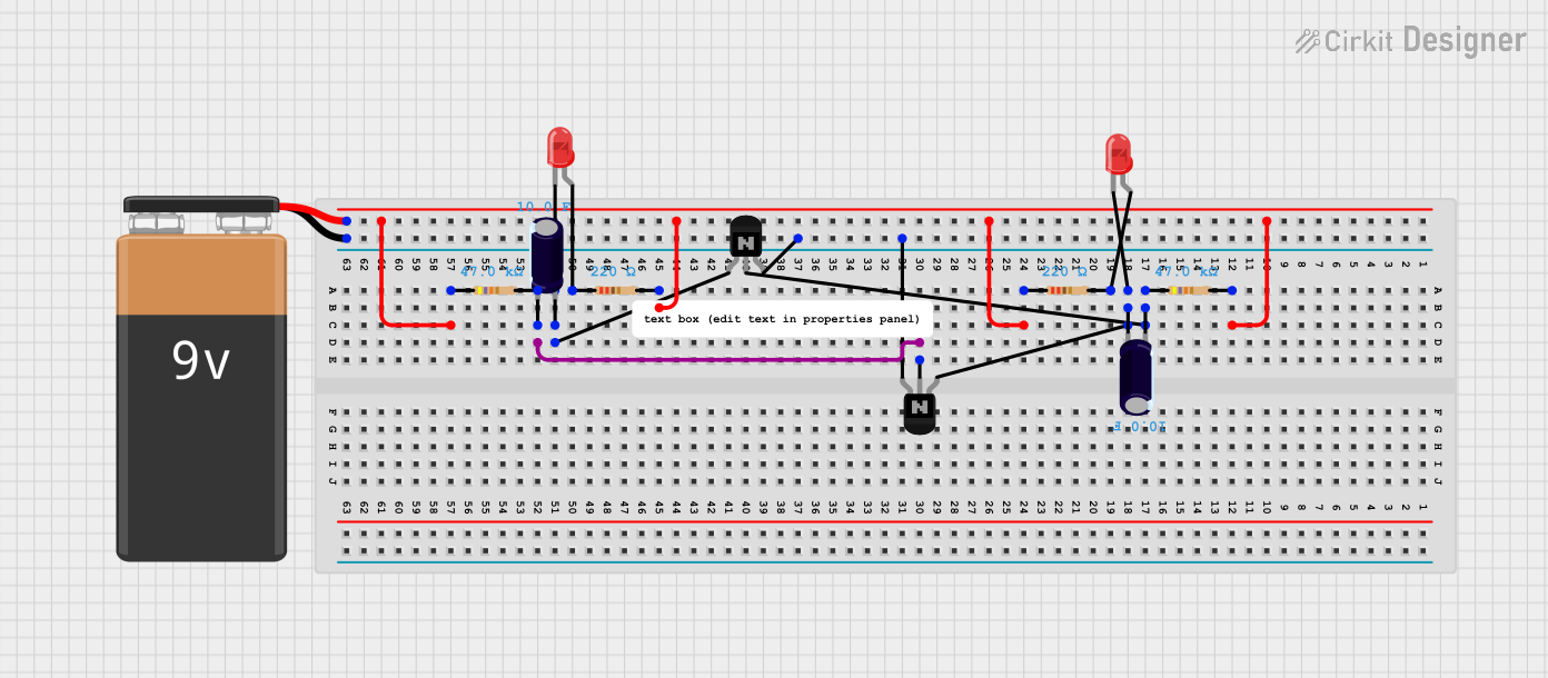
Example: Connecting a Circuit to an Arduino UNO
Below is an example of a simple LED circuit connected to an Arduino UNO:
Circuit Diagram
- Connect a 220-ohm resistor in series with an LED.
- Connect the anode (long leg) of the LED to digital pin 13 on the Arduino.
- Connect the cathode (short leg) of the LED to GND.
Arduino Code
// Simple LED Blink Program
// This program blinks an LED connected to pin 13 of the Arduino UNO.

void setup() {
  pinMode(13, OUTPUT); // Set pin 13 as an output pin
}

void loop() {
  digitalWrite(13, HIGH); // Turn the LED on
  delay(1000);            // Wait for 1 second
  digitalWrite(13, LOW);  // Turn the LED off
  delay(1000);            // Wait for 1 second
}
Troubleshooting and FAQs
Common Issues
Circuit Does Not Work:
- Cause: Loose connections or incorrect wiring.
- Solution: Double-check all connections against the schematic.
Component Overheating:
- Cause: Exceeding the component's voltage or current rating.
- Solution: Replace the component with one of a higher rating or reduce the power supply.
Short Circuit:
- Cause: Accidental connection between V+ and GND.
- Solution: Inspect the circuit for unintended connections and fix them.
LED Does Not Light Up:
- Cause: Incorrect polarity or insufficient current.
- Solution: Ensure the anode is connected to the positive voltage and use an appropriate resistor.
FAQs
Q: How do I calculate the resistor value for an LED?
A: Use Ohm's Law: ( R = \frac{V_{supply} - V_{LED}}{I_{LED}} ), where ( V_{supply} ) is the supply voltage, ( V_{LED} ) is the forward voltage of the LED, and ( I_{LED} ) is the desired current (typically 20mA for standard LEDs).
Q: Can I use a breadboard for high-power circuits?
A: No, breadboards are not suitable for high-power circuits due to their limited current capacity and potential for overheating.
Q: What tools are essential for building circuits?
A: Basic tools include a multimeter, soldering iron, wire cutters, and a breadboard or PCB.
By following this documentation, you can design, assemble, and troubleshoot circuits effectively for a wide range of applications.