How to Use Linear actuator: Examples, Pinouts, and Specs
Introduction
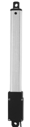
A linear actuator is a device that creates motion in a straight line, as opposed to the circular motion of a conventional electric motor. This type of actuator is commonly used in industrial machinery and robotics to convert electrical energy into mechanical movement. Linear actuators are essential in applications where precise control of linear motion is required, such as in automated manufacturing, medical devices, and aerospace systems.
Explore Projects Built with Linear actuator
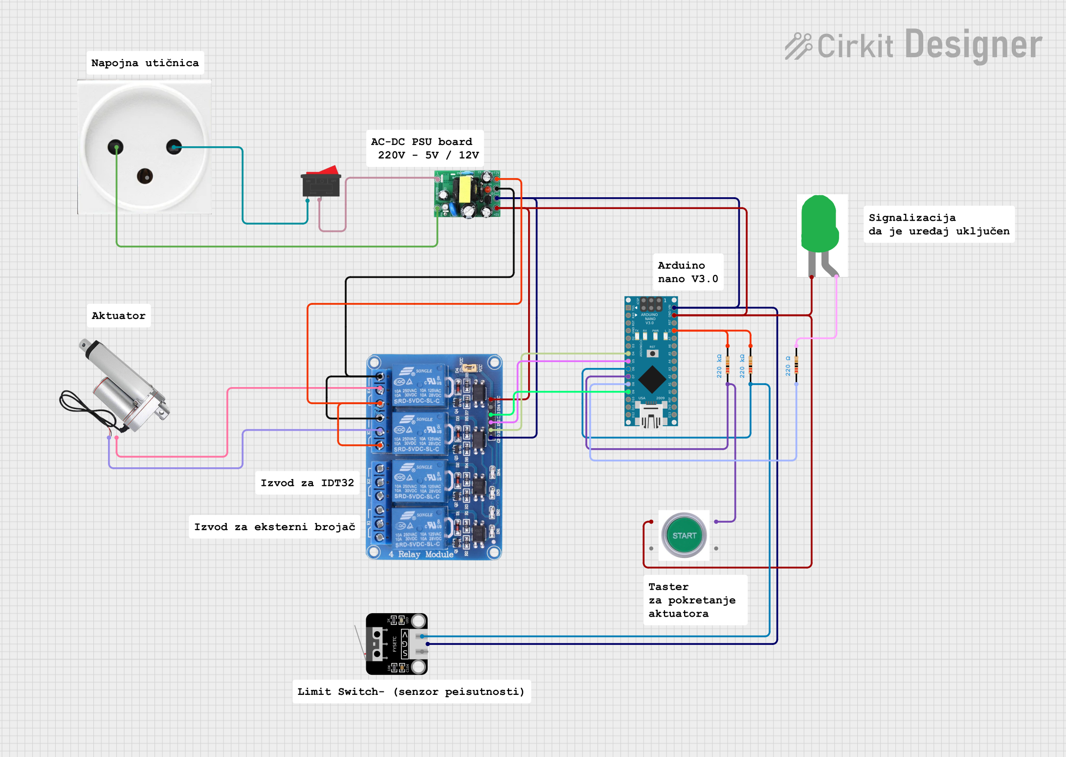
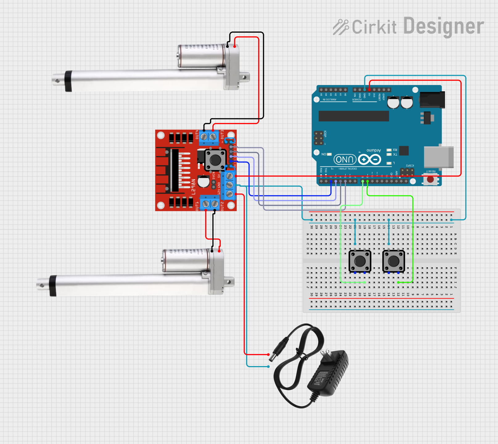
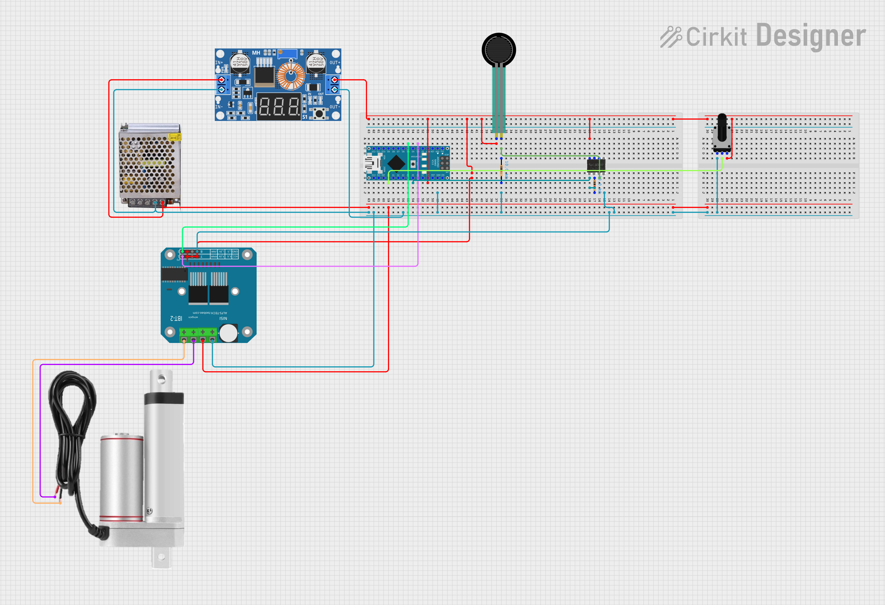
Explore Projects Built with Linear actuator
Technical Specifications
Key Technical Details
| Parameter | Value |
|---|---|
| Manufacturer | Arduino |
| Part ID | UNO |
| Voltage | 12V DC |
| Current | 2A |
| Stroke Length | 100mm |
| Load Capacity | 1000N (approximately 100kg) |
| Speed | 10mm/s |
| Duty Cycle | 25% |
| Operating Temperature | -10°C to 50°C |
Pin Configuration and Descriptions
| Pin Number | Pin Name | Description |
|---|---|---|
| 1 | VCC | Power supply (12V DC) |
| 2 | GND | Ground |
| 3 | IN1 | Control signal input 1 |
| 4 | IN2 | Control signal input 2 |
| 5 | POT | Potentiometer feedback (optional) |
Usage Instructions
How to Use the Component in a Circuit
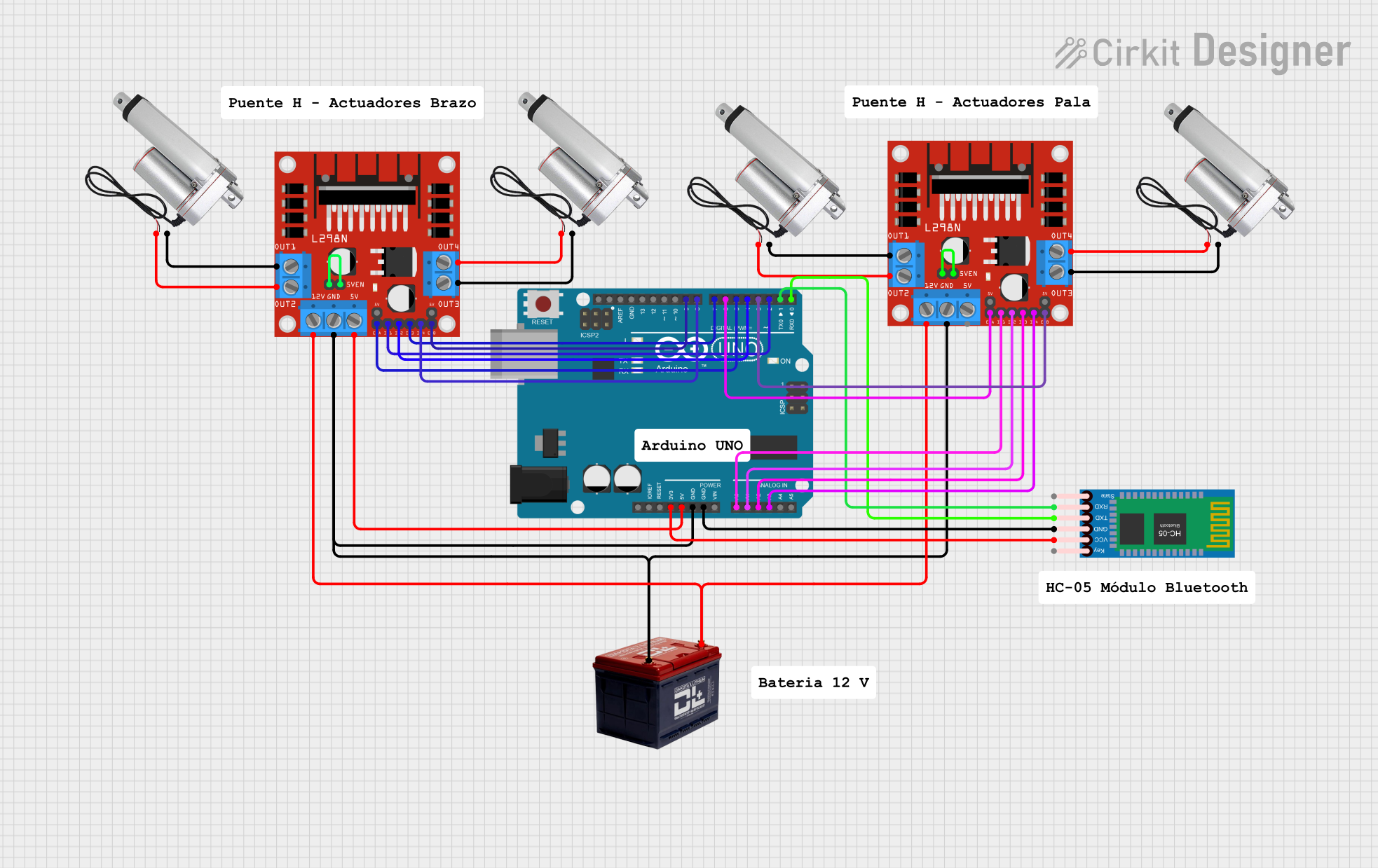
To use the linear actuator with an Arduino UNO, you will need an H-bridge motor driver (such as the L298N) to control the direction and speed of the actuator. Below is a basic wiring diagram and example code to get you started.
Wiring Diagram
- Connect the VCC pin of the linear actuator to the 12V power supply.
- Connect the GND pin of the linear actuator to the ground of the power supply.
- Connect the IN1 and IN2 pins of the linear actuator to the output pins of the H-bridge motor driver.
- Connect the control pins of the H-bridge motor driver to the digital pins of the Arduino UNO.
Example Code
// Define the control pins for the H-bridge motor driver
const int controlPin1 = 7; // IN1 connected to digital pin 7
const int controlPin2 = 8; // IN2 connected to digital pin 8

void setup() {
  // Set the control pins as outputs
  pinMode(controlPin1, OUTPUT);
  pinMode(controlPin2, OUTPUT);
}

void loop() {
  // Extend the linear actuator
  digitalWrite(controlPin1, HIGH);
  digitalWrite(controlPin2, LOW);
  delay(5000); // Extend for 5 seconds

  // Stop the linear actuator
  digitalWrite(controlPin1, LOW);
  digitalWrite(controlPin2, LOW);
  delay(2000); // Pause for 2 seconds

  // Retract the linear actuator
  digitalWrite(controlPin1, LOW);
  digitalWrite(controlPin2, HIGH);
  delay(5000); // Retract for 5 seconds

  // Stop the linear actuator
  digitalWrite(controlPin1, LOW);
  digitalWrite(controlPin2, LOW);
  delay(2000); // Pause for 2 seconds
}
Important Considerations and Best Practices
- Power Supply: Ensure that the power supply can provide sufficient current (2A) at 12V DC.
- Duty Cycle: The actuator has a duty cycle of 25%, meaning it should not be operated continuously for more than 25% of the time to avoid overheating.
- Load Capacity: Do not exceed the load capacity of 1000N to prevent damage to the actuator.
- Temperature Range: Operate the actuator within the specified temperature range (-10°C to 50°C) to ensure optimal performance.
Troubleshooting and FAQs
Common Issues Users Might Face
Actuator Not Moving:
- Solution: Check the power supply connections and ensure that the voltage is 12V DC. Verify that the control signals from the Arduino are correctly sent to the H-bridge motor driver.
Actuator Moving in One Direction Only:
- Solution: Ensure that both control pins (IN1 and IN2) are correctly connected to the H-bridge motor driver and that the driver is functioning properly.
Overheating:
- Solution: Check the duty cycle and ensure that the actuator is not operated continuously for more than 25% of the time. Allow the actuator to cool down before using it again.
Inconsistent Movement:
- Solution: Verify that the load does not exceed the actuator's capacity (1000N). Check for any obstructions or mechanical issues that may hinder the actuator's movement.
Solutions and Tips for Troubleshooting
- Check Connections: Ensure all electrical connections are secure and correctly wired.
- Use Proper Power Supply: Make sure the power supply meets the voltage and current requirements of the actuator.
- Monitor Temperature: Regularly check the actuator's temperature during operation to prevent overheating.
- Test Control Signals: Use a multimeter to verify that the control signals from the Arduino are correctly reaching the H-bridge motor driver.
By following this documentation, users should be able to effectively integrate and operate the Arduino UNO linear actuator in their projects, ensuring reliable and precise linear motion control.