How to Use SparkFun Blynk Board - ESP8266: Examples, Pinouts, and Specs
Introduction
The SparkFun Blynk Board - ESP8266 is an all-in-one wireless platform designed to simplify the development of Internet of Things (IoT) projects. Leveraging the capabilities of the ESP8266 Wi-Fi module, this board comes pre-programmed with Blynk firmware, allowing for quick and seamless integration with the Blynk mobile app platform. Users can control and monitor their projects remotely through a user-friendly interface on their smartphones or tablets. Common applications include home automation, sensor networks, and DIY electronics projects.
Explore Projects Built with SparkFun Blynk Board - ESP8266

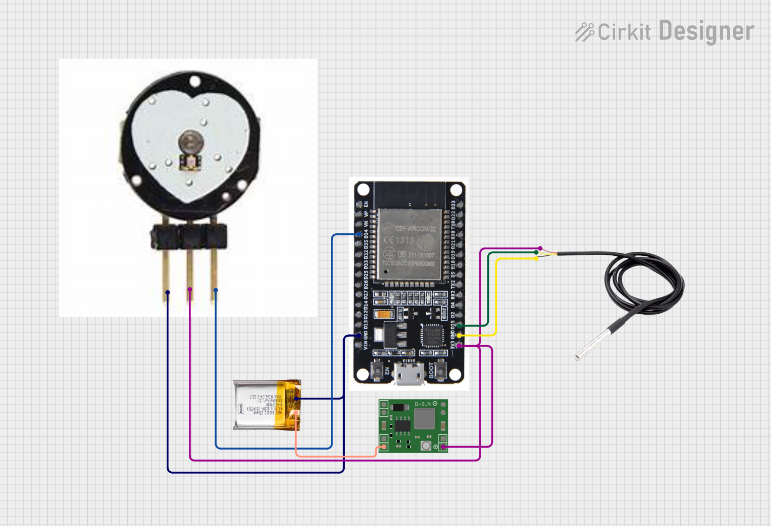
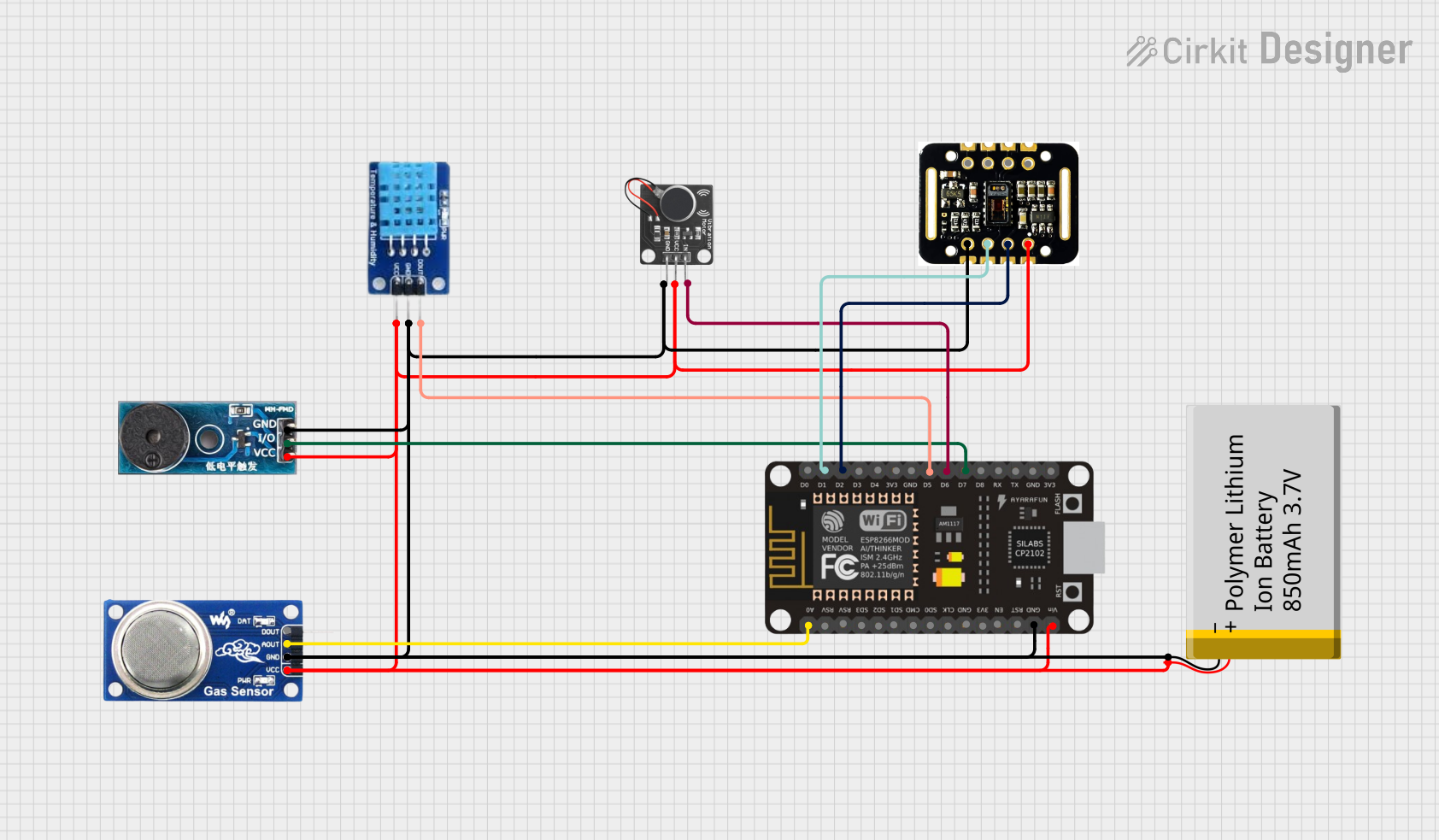
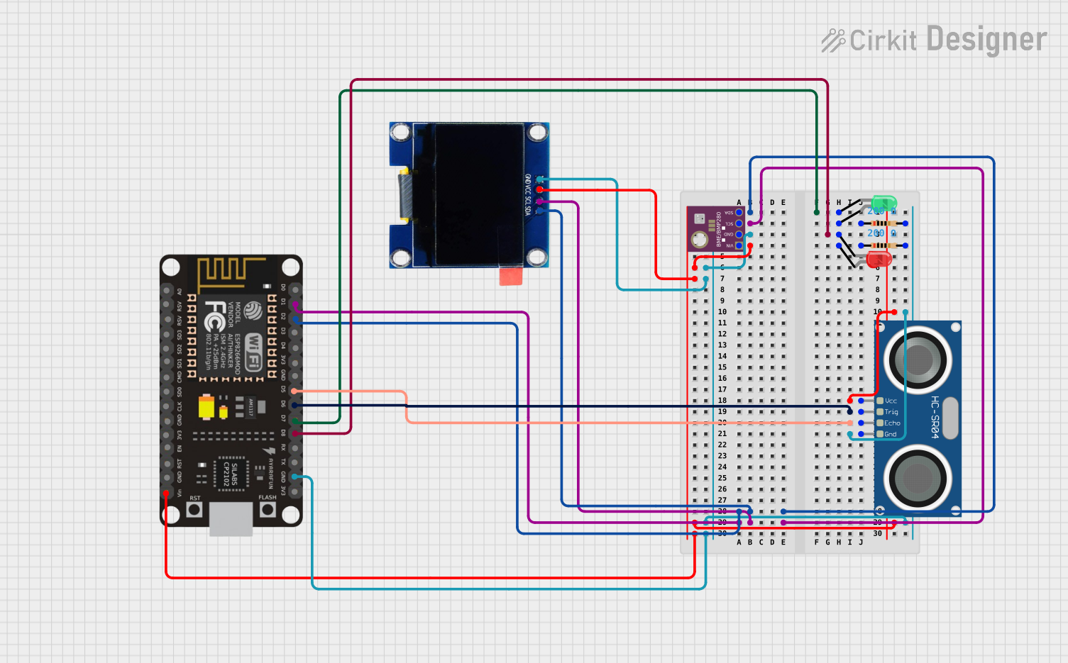
Explore Projects Built with SparkFun Blynk Board - ESP8266
Technical Specifications
Key Technical Details
- Wi-Fi Module: ESP8266
- Operating Voltage: 3.3V
- Input Voltage (recommended): 5V via micro USB
- Digital I/O Pins: 9, with PWM capability
- Analog Input Pins: 1 (0-1V)
- Flash Memory: 4MB
- Wi-Fi Standards: 802.11 b/g/n
- Frequency Range: 2.4 GHz - 2.5 GHz
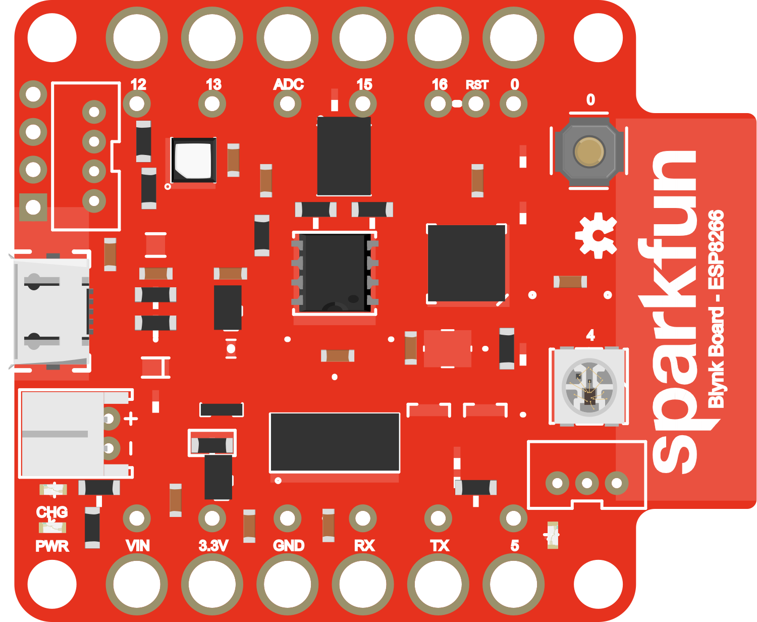
Pin Configuration and Descriptions
| Pin Number | Function | Description |
|---|---|---|
| 1 | GND | Ground |
| 2 | 3V3 | 3.3V power supply |
| 3 | EN | Chip enable; active high |
| 4 | RST | Reset pin; active low |
| 5-13 | GPIO0 - GPIO8 | General Purpose Input/Output pins |
| A0 | ADC | Analog to Digital Converter input (0-1V) |
Usage Instructions
Integrating with a Circuit
- Powering the Board: Connect a 5V power supply to the micro USB port.
- Connecting to Wi-Fi: Use the Blynk app to configure the board to connect to your local Wi-Fi network.
- Attaching Peripherals: Connect sensors or actuators to the GPIO pins as required for your project.
Important Considerations and Best Practices
- Ensure that the input voltage does not exceed the recommended 5V to prevent damage.
- Use a level shifter if you need to interface the board with 5V logic components.
- Avoid drawing more than 12 mA from any GPIO pin.
- When programming the board, ensure that GPIO0 is grounded to enable the bootloader mode.
Example Code for Arduino UNO
// This example demonstrates a simple integration with an Arduino UNO
// to toggle an LED using the Blynk app.

#include <ESP8266WiFi.h>
#include <BlynkSimpleEsp8266.h>

// Your WiFi credentials.
char ssid[] = "YourNetworkName";
char pass[] = "YourPassword";

// Your Blynk auth token.
char auth[] = "YourAuthToken";

void setup() {
  // Set up serial communication at a baud rate of 9600.
  Serial.begin(9600);
  Blynk.begin(auth, ssid, pass);
}

void loop() {
  Blynk.run();
}

// In the Blynk app, create a button that writes to virtual pin V1
BLYNK_WRITE(V1) {
  int pinValue = param.asInt(); // Assigning incoming value from pin V1 to a variable
  // You can also use: if (param.asInt()) { ... }
  digitalWrite(13, pinValue); // Sets the LED on GPIO13 to HIGH or LOW
}
Troubleshooting and FAQs
Common Issues
- Board not connecting to Wi-Fi: Ensure that the SSID and password are correctly entered in the code. Check the Wi-Fi signal strength and router settings.
- Unable to upload code: Verify that the correct board and port are selected in the Arduino IDE. Ensure that GPIO0 is grounded when resetting the board to enter bootloader mode.
- Peripherals not working: Check the wiring and ensure that the peripherals are compatible with the board's voltage levels.
Solutions and Tips
- Resetting the Board: If the board becomes unresponsive, use the RST pin to reset it.
- Serial Monitor: Use the serial monitor in the Arduino IDE to debug and monitor the board's output.
- Blynk Community: Join the Blynk community forums for additional support and project ideas.
FAQs
Q: Can I power the Blynk Board using a battery? A: Yes, you can power the board using a 3.3V battery, but ensure that the voltage does not drop below the minimum operating voltage.
Q: How many devices can I control with the Blynk app? A: The Blynk app can control multiple devices, but each device requires its own auth token.
Q: Is the Blynk Board compatible with Arduino IDE? A: Yes, the board can be programmed using the Arduino IDE with the appropriate ESP8266 board package installed.