How to Use 3-Axis Sensor: Examples, Pinouts, and Specs
Introduction
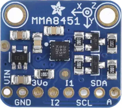
The 3-Axis Sensor (MMA8451), manufactured by Adafruit Industries, is a high-precision accelerometer designed to measure acceleration or angular velocity along three perpendicular axes (X, Y, and Z). This sensor is widely used in motion detection, orientation sensing, and tilt measurement applications. Its compact size, low power consumption, and high sensitivity make it ideal for use in consumer electronics, robotics, and IoT devices.
Explore Projects Built with 3-Axis Sensor


Explore Projects Built with 3-Axis Sensor
Common Applications and Use Cases
- Motion detection in smartphones and wearables
- Orientation sensing for robotics and drones
- Tilt and vibration measurement in industrial systems
- Step counting and activity tracking in fitness devices
- Gaming controllers and virtual reality systems
Technical Specifications
The MMA8451 is a versatile and feature-rich accelerometer. Below are its key technical specifications:
| Parameter | Value |
|---|---|
| Operating Voltage | 1.95V to 3.6V |
| Communication Interface | I2C |
| Measurement Range | ±2g, ±4g, ±8g (configurable) |
| Resolution | 14-bit |
| Output Data Rate (ODR) | 1.56 Hz to 800 Hz |
| Operating Temperature | -40°C to +85°C |
| Power Consumption | 6 µA (low-power mode) |
| Dimensions | 3 mm x 3 mm x 1 mm |
Pin Configuration and Descriptions
The MMA8451 sensor typically comes in a breakout board format for ease of use. Below is the pinout for the Adafruit MMA8451 breakout board:
| Pin Name | Description |
|---|---|
| VIN | Power input (3.3V or 5V) |
| GND | Ground connection |
| SCL | I2C clock line (connect to Arduino's A5 or dedicated SCL pin) |
| SDA | I2C data line (connect to Arduino's A4 or dedicated SDA pin) |
| INT1 | Interrupt 1 output (optional, for motion detection or data-ready signals) |
| INT2 | Interrupt 2 output (optional, for additional interrupt configurations) |
Usage Instructions
How to Use the Component in a Circuit
- Power the Sensor: Connect the VIN pin to a 3.3V or 5V power source and the GND pin to ground.
- Connect I2C Lines: Connect the SDA and SCL pins to the corresponding I2C pins on your microcontroller (e.g., Arduino UNO).
- Optional Interrupts: If you need to use interrupts, connect INT1 and/or INT2 to digital input pins on your microcontroller.
- Install Required Libraries: For Arduino, install the Adafruit MMA8451 library via the Arduino Library Manager.
- Write Code: Use the library functions to initialize the sensor, configure settings, and read acceleration data.
Important Considerations and Best Practices
- Voltage Compatibility: Ensure the sensor's operating voltage matches your microcontroller's I2C voltage levels. Use level shifters if necessary.
- Pull-Up Resistors: The I2C lines (SDA and SCL) require pull-up resistors. These are typically included on the breakout board.
- Mounting Orientation: Properly align the sensor to ensure accurate readings. The X, Y, and Z axes are marked on the breakout board.
- Noise Filtering: Use the built-in high-pass filter to reduce noise in acceleration measurements.
Example Code for Arduino UNO
Below is an example Arduino sketch to read acceleration data from the MMA8451 sensor:
#include <Wire.h>
#include <Adafruit_MMA8451.h>
#include <Adafruit_Sensor.h>

// Create an instance of the MMA8451 class
Adafruit_MMA8451 mma = Adafruit_MMA8451();

void setup() {
  Serial.begin(9600); // Initialize serial communication at 9600 baud
  Serial.println("MMA8451 Test!");

  // Initialize the sensor
  if (!mma.begin()) {
    Serial.println("Could not find a valid MMA8451 sensor, check wiring!");
    while (1); // Halt execution if sensor is not found
  }

  Serial.println("MMA8451 Found!");

  // Set the measurement range to ±2g
  mma.setRange(MMA8451_RANGE_2_G);
  Serial.print("Range set to: ");
  switch (mma.getRange()) {
    case MMA8451_RANGE_2_G: Serial.println("±2g"); break;
    case MMA8451_RANGE_4_G: Serial.println("±4g"); break;
    case MMA8451_RANGE_8_G: Serial.println("±8g"); break;
  }
}

void loop() {
  // Read acceleration data
  sensors_event_t event;
  mma.getEvent(&event);

  // Print acceleration values for X, Y, and Z axes
  Serial.print("X: "); Serial.print(event.acceleration.x); Serial.print(" m/s^2 ");
  Serial.print("Y: "); Serial.print(event.acceleration.y); Serial.print(" m/s^2 ");
  Serial.print("Z: "); Serial.print(event.acceleration.z); Serial.println(" m/s^2");

  delay(500); // Wait 500ms before the next reading
}
Troubleshooting and FAQs
Common Issues and Solutions
Sensor Not Detected
- Cause: Incorrect wiring or I2C address mismatch.
- Solution: Double-check the connections and ensure the I2C address (default: 0x1D) matches the library settings.
No Data or Incorrect Readings
- Cause: Improper power supply or loose connections.
- Solution: Verify the power supply voltage and ensure all connections are secure.
High Noise in Readings
- Cause: Environmental vibrations or electrical noise.
- Solution: Enable the sensor's high-pass filter or average multiple readings in software.
Interrupts Not Working
- Cause: Interrupt pins not configured correctly.
- Solution: Check the interrupt configuration in the library and ensure the INT pins are connected to the correct microcontroller pins.
FAQs
Q: Can the MMA8451 measure angular velocity?
A: No, the MMA8451 is an accelerometer and measures linear acceleration. For angular velocity, use a gyroscope.
Q: What is the maximum sampling rate of the sensor?
A: The MMA8451 supports an output data rate (ODR) of up to 800 Hz.
Q: Can I use this sensor with a 5V microcontroller?
A: Yes, the breakout board includes level shifting circuitry, making it compatible with 5V systems.
Q: How do I change the measurement range?
A: Use the setRange() function in the Adafruit MMA8451 library to configure the range to ±2g, ±4g, or ±8g.
Q: Is the sensor suitable for battery-powered applications?
A: Yes, the MMA8451 has a low-power mode that consumes only 6 µA, making it ideal for battery-powered devices.