How to Use Breaker 2A: Examples, Pinouts, and Specs
Introduction
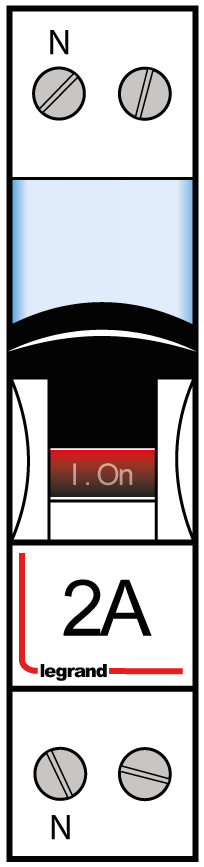
The Breaker 2A by Legrand is a circuit breaker rated for 2 Amperes, designed to protect electrical circuits from overloads and short circuits. It automatically interrupts the flow of current when the current exceeds its rated capacity, ensuring the safety of connected devices and preventing potential damage to electrical systems.
Explore Projects Built with Breaker 2A
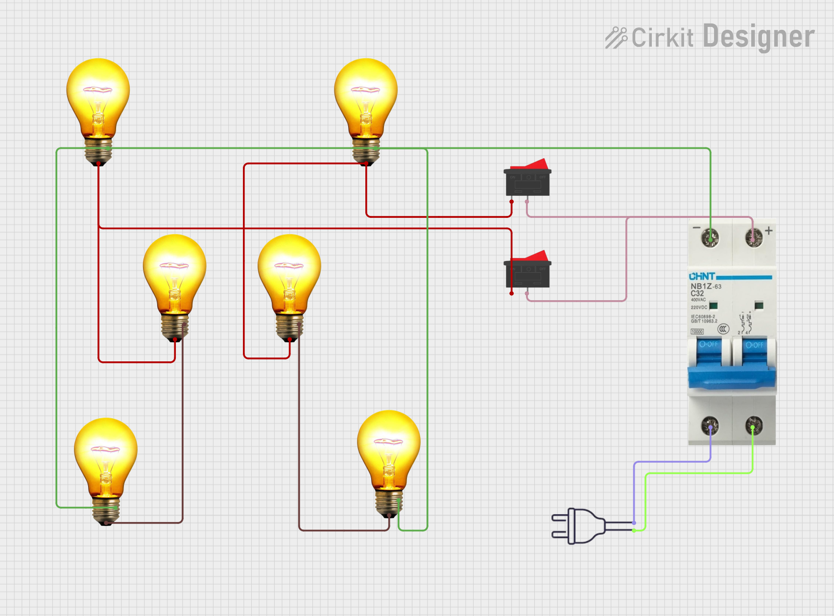
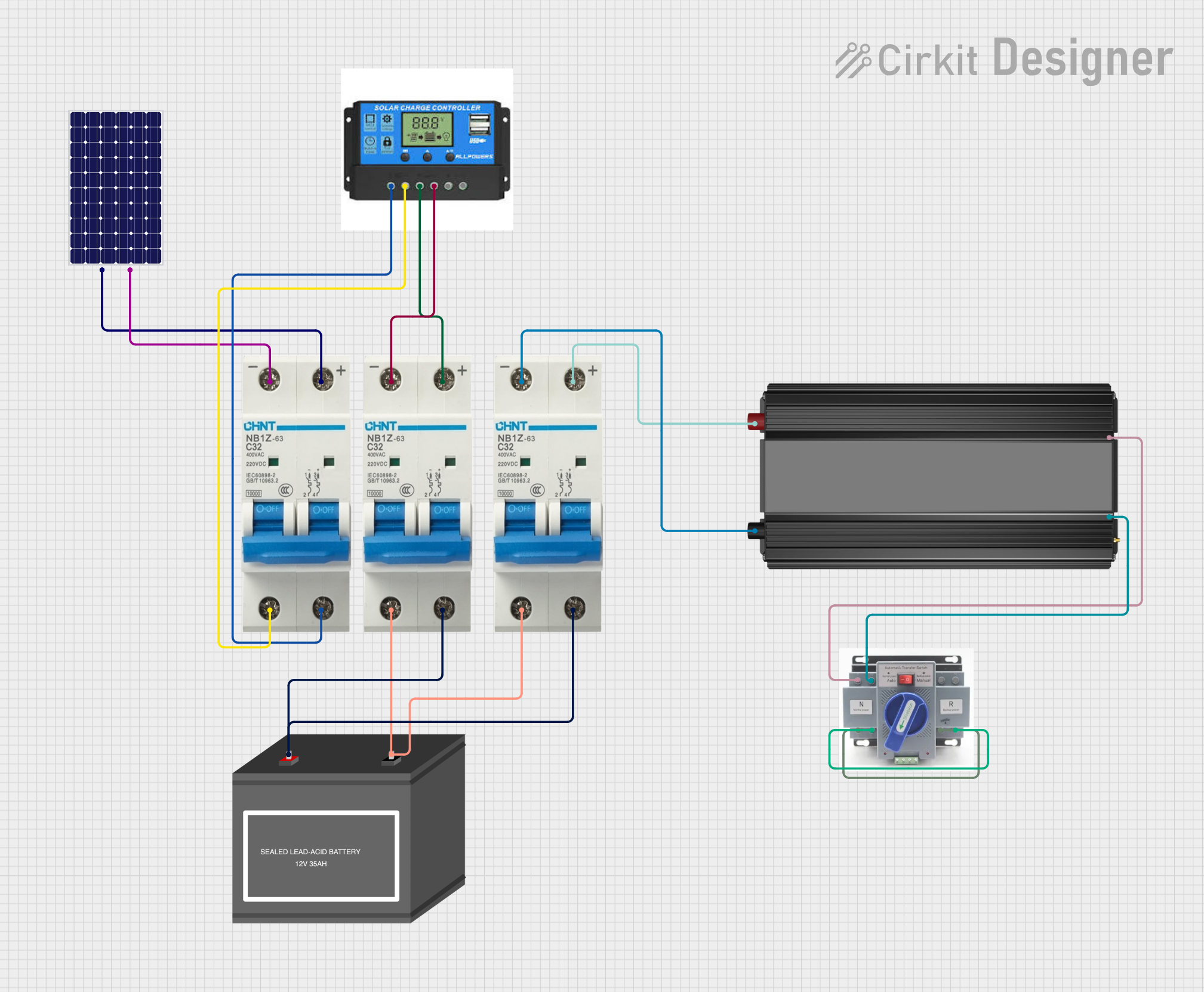

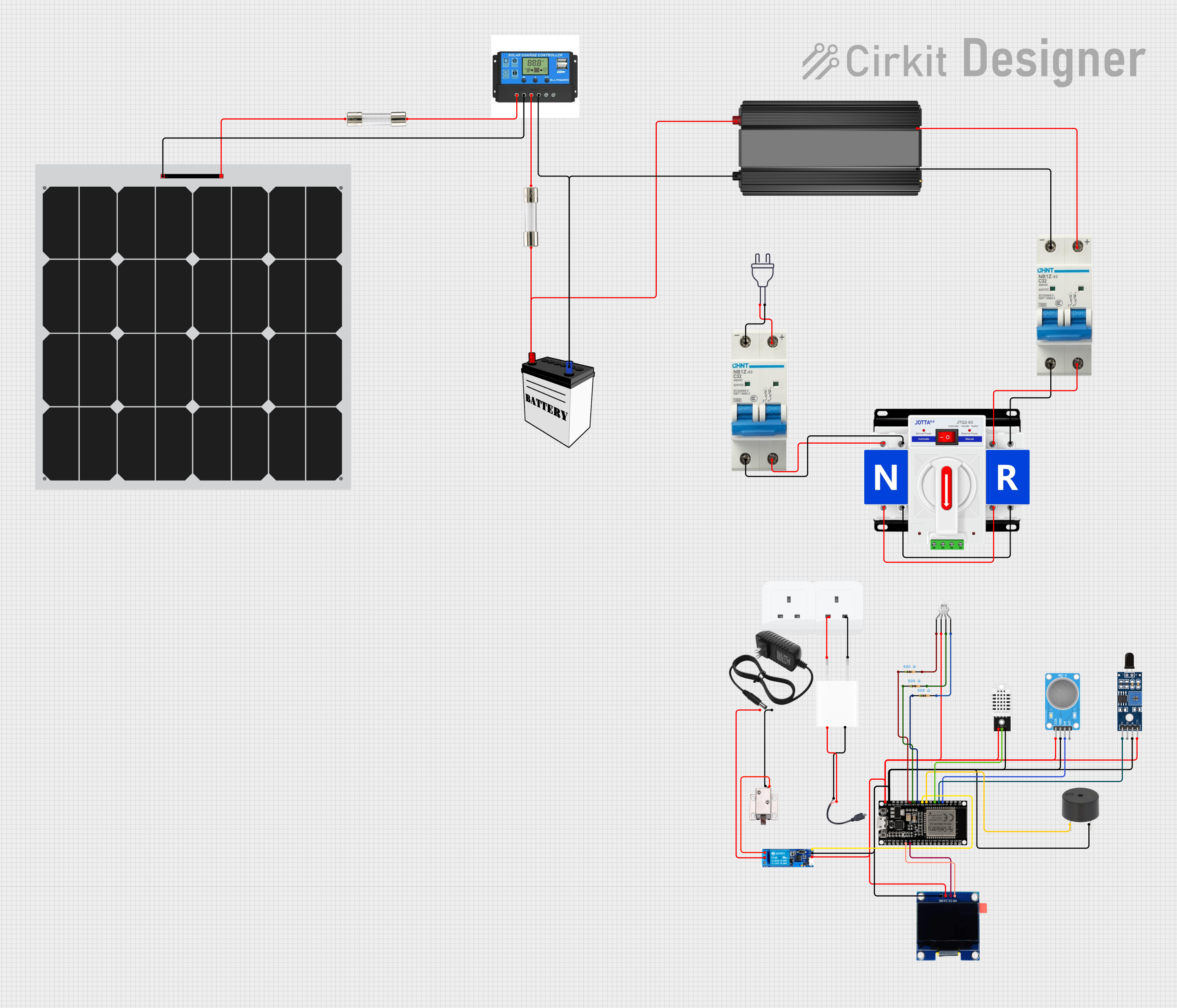
Explore Projects Built with Breaker 2A
Common Applications and Use Cases
- Protection of low-power electrical circuits in residential, commercial, and industrial settings.
- Safeguarding sensitive electronic devices from overcurrent conditions.
- Use in lighting circuits, small appliances, and control panels.
- Integration into DIY projects and prototyping setups for current protection.
Technical Specifications
The following table outlines the key technical details of the Breaker 2A:
| Specification | Details |
|---|---|
| Rated Current | 2 Amperes |
| Rated Voltage | 240V AC (single-phase) |
| Breaking Capacity | 6 kA |
| Type | Miniature Circuit Breaker (MCB) |
| Tripping Curve | Type C (moderate inrush current) |
| Operating Temperature | -5°C to +40°C |
| Mounting Type | DIN Rail (35mm standard) |
| Dimensions (HxWxD) | 81mm x 18mm x 70mm |
| Compliance Standards | IEC 60898-1, RoHS compliant |
Pin Configuration and Descriptions
The Breaker 2A has two connection terminals for input and output. The table below describes the terminals:
| Terminal | Description |
|---|---|
| Line (Input) | Connects to the live wire from the power source. |
| Load (Output) | Connects to the circuit or device being protected. |
Usage Instructions
How to Use the Breaker 2A in a Circuit
Mounting the Breaker:
- Install the breaker on a standard 35mm DIN rail in your distribution box or panel.
- Ensure the breaker is securely locked into place.
Wiring the Breaker:
- Connect the Line (Input) terminal to the live wire from the power source.
- Connect the Load (Output) terminal to the circuit or device you want to protect.
- Tighten the terminal screws to ensure a secure connection. Avoid overtightening.
Testing the Breaker:
- After installation, switch the breaker to the "ON" position.
- Test the breaker by simulating an overload or short circuit (if safe to do so) to ensure it trips correctly.
Resetting the Breaker:
- If the breaker trips, identify and resolve the cause of the overload or short circuit.
- Once resolved, switch the breaker to the "OFF" position, then back to "ON" to reset it.
Important Considerations and Best Practices
- Ensure the breaker is rated appropriately for the circuit's current requirements (2A max).
- Do not exceed the rated voltage (240V AC) or breaking capacity (6 kA).
- Regularly inspect the breaker for signs of wear, damage, or loose connections.
- Avoid using the breaker in environments with extreme temperatures or high humidity.
- For Arduino or other low-voltage applications, use a step-down transformer or DC-DC converter to interface with the breaker safely.
Example: Using the Breaker 2A with an Arduino UNO
While the Breaker 2A is primarily designed for AC circuits, it can be used in low-voltage DC circuits with proper precautions. Below is an example of how to integrate the breaker into a 12V DC circuit controlled by an Arduino UNO:
/*
  Example: Using Breaker 2A in a 12V DC circuit with Arduino UNO
  This code demonstrates how to monitor the status of a circuit protected
  by the Breaker 2A using a digital input pin on the Arduino.
*/

const int breakerPin = 2; // Digital pin connected to the breaker status output
const int ledPin = 13;    // Built-in LED to indicate breaker status

void setup() {
  pinMode(breakerPin, INPUT_PULLUP); // Configure breakerPin as input with pull-up
  pinMode(ledPin, OUTPUT);           // Configure ledPin as output
  Serial.begin(9600);                // Initialize serial communication
}

void loop() {
  int breakerStatus = digitalRead(breakerPin); // Read breaker status

  if (breakerStatus == HIGH) {
    // Breaker is in the "ON" position
    digitalWrite(ledPin, HIGH); // Turn on LED
    Serial.println("Breaker is ON. Circuit is active.");
  } else {
    // Breaker is in the "OFF" position (tripped)
    digitalWrite(ledPin, LOW);  // Turn off LED
    Serial.println("Breaker is OFF. Circuit is inactive.");
  }

  delay(500); // Wait for 500ms before next status check
}
Note: In this example, the breaker status is monitored using a digital input pin. Ensure proper isolation and voltage level shifting when interfacing with the Arduino.
Troubleshooting and FAQs
Common Issues and Solutions
| Issue | Possible Cause | Solution |
|---|---|---|
| Breaker trips frequently | Circuit overload or short circuit | Check the connected load and wiring. Ensure the load does not exceed 2A. |
| Breaker does not trip during overload | Faulty breaker or incorrect installation | Verify wiring and test the breaker. Replace if necessary. |
| Breaker does not reset after tripping | Persistent fault in the circuit | Inspect the circuit for faults and resolve them before resetting. |
| Loose connections at terminals | Improper tightening of terminal screws | Re-tighten the screws securely. Avoid overtightening. |
FAQs
Can the Breaker 2A be used for DC circuits?
Yes, but ensure the voltage and current ratings are within safe limits for DC applications.What is the difference between Type C and Type B breakers?
Type C breakers are designed to handle moderate inrush currents, making them suitable for circuits with inductive loads like motors. Type B breakers are more sensitive and trip at lower inrush currents.How often should the breaker be tested?
It is recommended to test the breaker at least once a year to ensure proper functionality.Can I use the Breaker 2A for a 3-phase system?
No, the Breaker 2A is designed for single-phase systems only. Use a 3-phase breaker for such applications.