How to Use Relay PYF-14: Examples, Pinouts, and Specs
Introduction
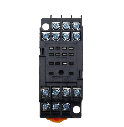
The Relay PYF-14 is a modular relay socket designed for easy installation and replacement of relays in various electrical circuits. Manufactured by 230V, this component provides a secure and reliable connection for relays, ensuring efficient operation in automation and control systems. Its modular design allows for quick wiring changes, making it a versatile choice for industrial and commercial applications.
Explore Projects Built with Relay PYF-14
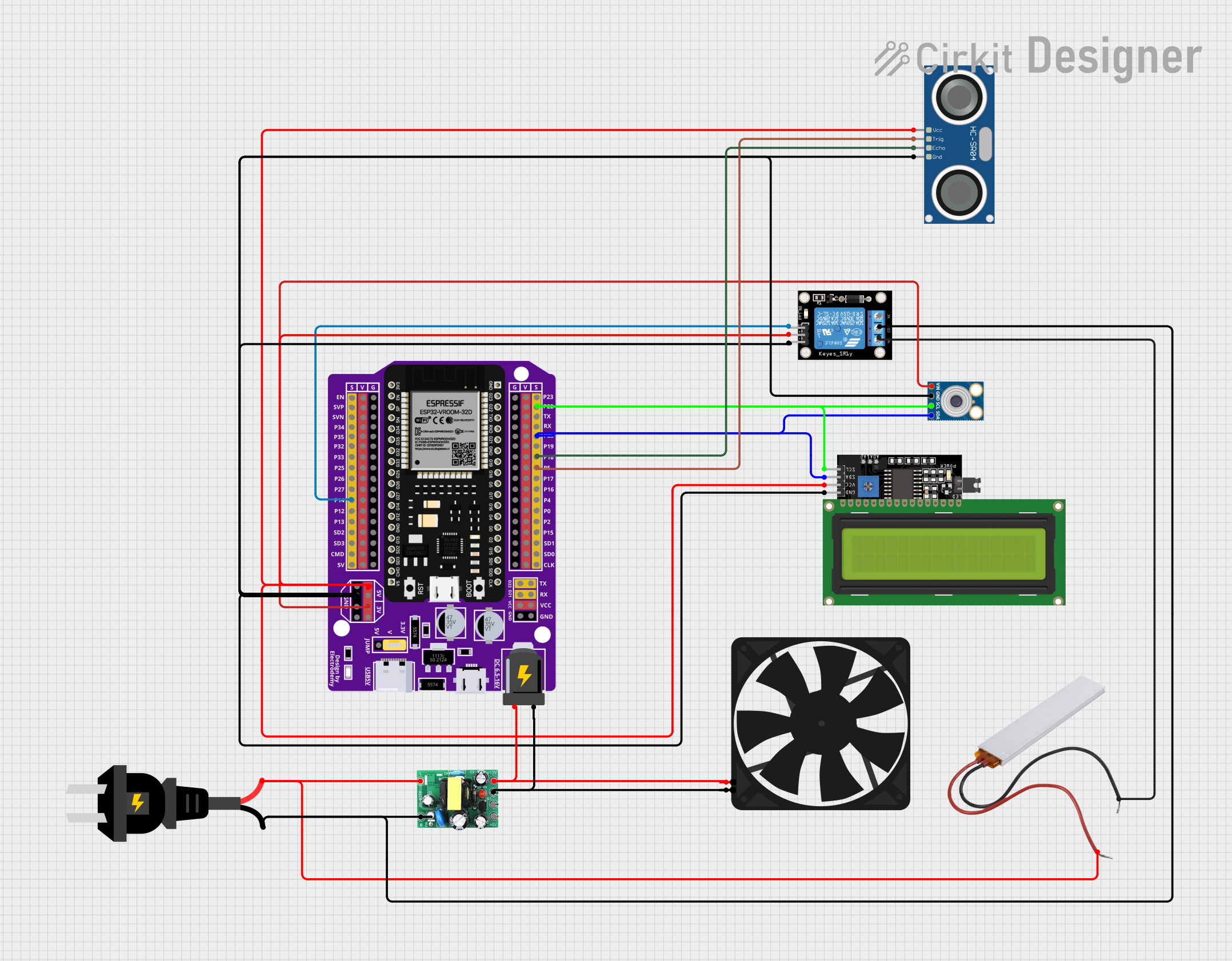
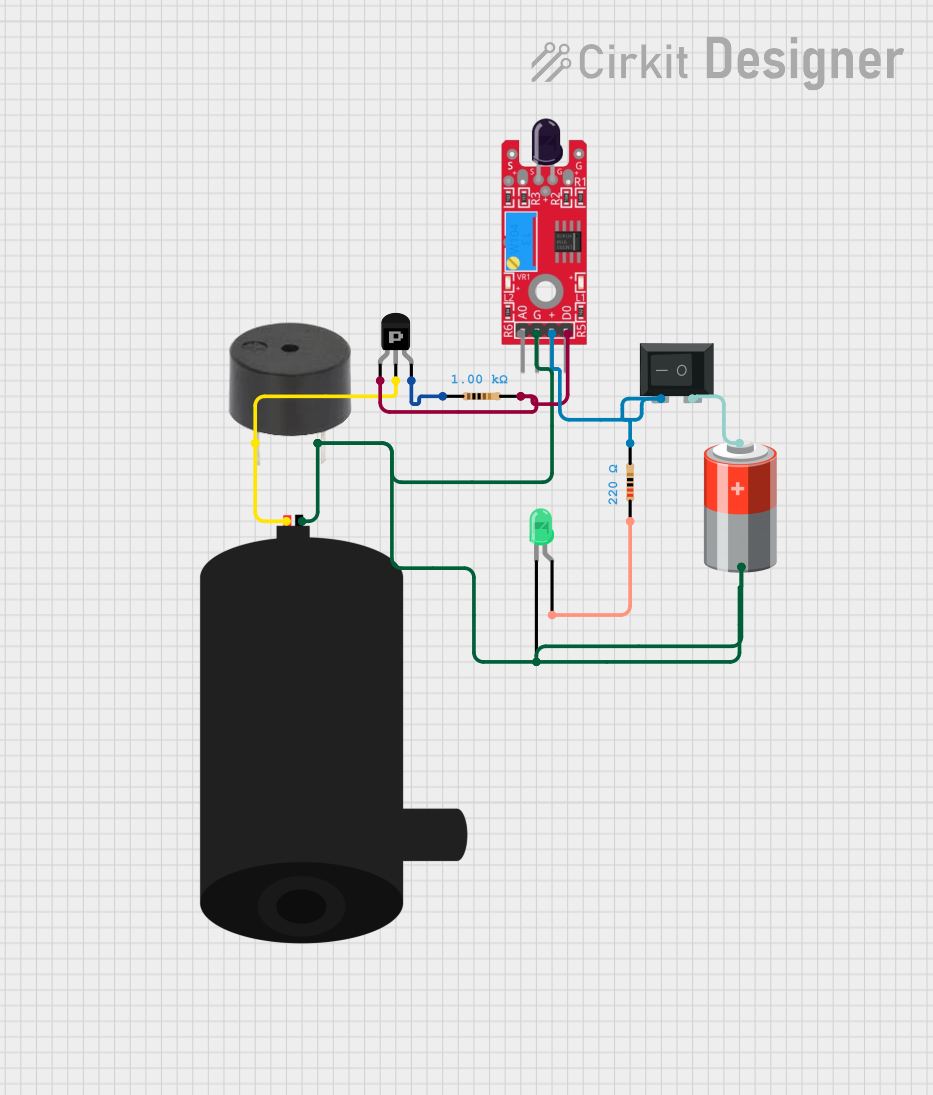


Explore Projects Built with Relay PYF-14
Common Applications and Use Cases
- Industrial automation systems
- Control panels and switchboards
- HVAC systems
- Motor control circuits
- Lighting control systems
- Power distribution and monitoring
Technical Specifications
The Relay PYF-14 is designed to work with standard plug-in relays and offers robust performance in demanding environments. Below are the key technical details:
General Specifications
| Parameter | Value |
|---|---|
| Manufacturer | 230V |
| Part ID | PYF-14 |
| Rated Voltage | 250V AC / 30V DC |
| Maximum Current | 10A |
| Contact Configuration | 4PDT (Four Pole Double Throw) |
| Operating Temperature | -40°C to 70°C |
| Mounting Type | DIN Rail or Panel Mount |
| Material | Flame-retardant plastic |
Pin Configuration and Descriptions
The PYF-14 socket features 14 pins, which correspond to the relay's contacts. Below is the pin configuration:
| Pin Number | Description |
|---|---|
| 1, 2 | Coil Terminals (A1, A2) |
| 3, 4 | Common Contact (Pole 1) |
| 5, 6 | Normally Open (NO) Contact 1 |
| 7, 8 | Normally Closed (NC) Contact 1 |
| 9, 10 | Common Contact (Pole 2) |
| 11, 12 | Normally Open (NO) Contact 2 |
| 13, 14 | Normally Closed (NC) Contact 2 |
Usage Instructions
How to Use the Relay PYF-14 in a Circuit
- Mounting the Socket: Secure the PYF-14 socket onto a DIN rail or panel using the appropriate mounting hardware.
- Wiring the Socket:
- Connect the relay coil terminals (A1 and A2) to the control circuit.
- Wire the common (COM), normally open (NO), and normally closed (NC) terminals to the load and power source as per your circuit design.
- Inserting the Relay: Plug the compatible relay into the PYF-14 socket, ensuring proper alignment of the pins.
- Testing the Circuit: Power on the circuit and verify the relay operation by activating the control signal.
Important Considerations and Best Practices
- Ensure the relay used is compatible with the PYF-14 socket in terms of pin configuration and electrical ratings.
- Double-check all connections for proper polarity and secure wiring to avoid loose contacts.
- Use appropriate wire gauges for the current rating of the circuit.
- Avoid exceeding the rated voltage and current to prevent damage to the socket or relay.
- If using the socket in a high-vibration environment, consider using a relay retaining clip for added stability.
Example: Connecting to an Arduino UNO
The Relay PYF-14 can be used with an Arduino UNO to control high-power devices. Below is an example circuit and code:
Circuit Description
- Connect the relay coil terminals (A1 and A2) to a 5V relay driver circuit (e.g., a transistor and diode setup).
- Use a digital output pin from the Arduino to control the relay driver circuit.
Arduino Code
// Example code to control a relay using Arduino UNO
// Pin 7 is used to control the relay

const int relayPin = 7; // Define the pin connected to the relay driver

void setup() {
  pinMode(relayPin, OUTPUT); // Set the relay pin as an output
  digitalWrite(relayPin, LOW); // Ensure the relay is off initially
}

void loop() {
  digitalWrite(relayPin, HIGH); // Turn the relay on
  delay(1000); // Keep it on for 1 second
  digitalWrite(relayPin, LOW); // Turn the relay off
  delay(1000); // Keep it off for 1 second
}
Troubleshooting and FAQs
Common Issues and Solutions
Relay Does Not Activate:
- Cause: Incorrect wiring or insufficient control voltage.
- Solution: Verify the wiring and ensure the control voltage matches the relay's coil voltage.
Loose Connections:
- Cause: Improperly secured wires or relay.
- Solution: Check all connections and ensure the relay is firmly seated in the socket.
Overheating:
- Cause: Exceeding the rated current or voltage.
- Solution: Ensure the load does not exceed the socket's specifications.
Intermittent Operation:
- Cause: Vibration or poor contact.
- Solution: Use a retaining clip and inspect the socket for damage.
FAQs
Q: Can the PYF-14 socket be used with DC relays?
A: Yes, as long as the relay's pin configuration and electrical ratings are compatible with the socket.
Q: Is the PYF-14 socket suitable for outdoor use?
A: The socket is not weatherproof. Use it in a protected environment or within an enclosure for outdoor applications.
Q: What is the maximum wire size supported by the terminal screws?
A: The terminal screws can accommodate wires up to 12 AWG.
Q: Can I use the PYF-14 socket without a DIN rail?
A: Yes, the socket can also be panel-mounted using screws.