How to Use Servo2040: Examples, Pinouts, and Specs
Introduction
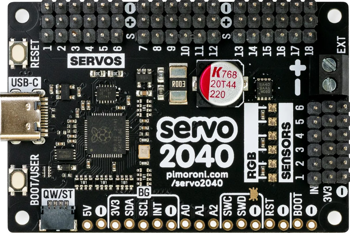
The Servo2040, manufactured by Pimoroni (Part ID: 2040), is a versatile microcontroller board tailored for robotics and automation projects. It is powered by the ARM Cortex-M0+ processor and features multiple GPIO pins with PWM support, making it an excellent choice for controlling servo motors, actuators, and other peripherals. Its compact design and robust capabilities make it ideal for hobbyists, educators, and professionals working on robotics, animatronics, or automated systems.
Explore Projects Built with Servo2040


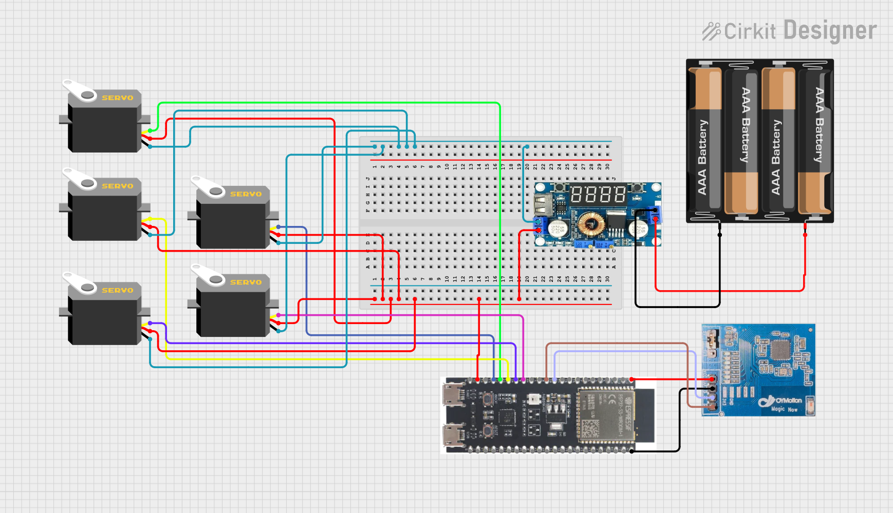
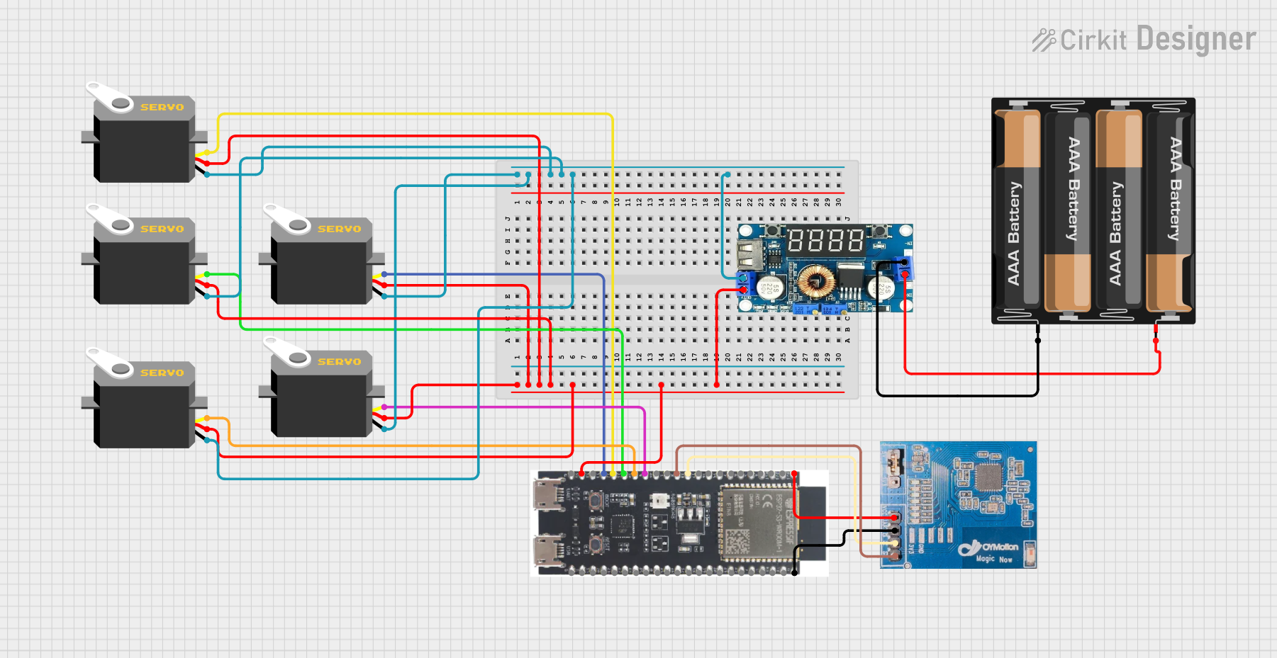
Explore Projects Built with Servo2040
Common Applications
- Robotics projects requiring precise servo motor control
- Animatronics and motion-based displays
- Automated systems and industrial control
- Educational projects for learning about PWM and microcontroller programming
- Prototyping servo-driven mechanisms
Technical Specifications
Key Technical Details
| Specification | Value |
|---|---|
| Processor | ARM Cortex-M0+ (RP2040) |
| Operating Voltage | 3.3V |
| Input Voltage Range | 5V (via USB-C) |
| GPIO Pins | 18 (with PWM support) |
| Servo Channels | 18 (dedicated PWM outputs for servos) |
| Communication Interfaces | I2C, SPI, UART |
| USB Interface | USB-C |
| Dimensions | 60mm x 25mm |
| Mounting Holes | 4 (M2.5 screws) |
Pin Configuration and Descriptions
The Servo2040 features 18 GPIO pins, each capable of PWM output for servo control. Below is the pinout description:
| Pin Number | Pin Name | Functionality |
|---|---|---|
| 1 | 3V3 | 3.3V Power Output |
| 2 | GND | Ground |
| 3 | GPIO0 | PWM, Digital I/O, I2C SDA |
| 4 | GPIO1 | PWM, Digital I/O, I2C SCL |
| 5 | GPIO2 | PWM, Digital I/O |
| 6 | GPIO3 | PWM, Digital I/O |
| ... | ... | ... (up to GPIO17) |
| 18 | GPIO17 | PWM, Digital I/O |
Usage Instructions
Using the Servo2040 in a Circuit
- Powering the Board: Connect the Servo2040 to a 5V power source via the USB-C port. Ensure the power supply can handle the current requirements of the connected servos.
- Connecting Servos: Attach servo motors to the GPIO pins. Each GPIO pin supports PWM output, which is essential for controlling servo positions.
- Programming the Board: Use MicroPython or C++ to program the Servo2040. The board is compatible with the Raspberry Pi Pico SDK, making it easy to write and upload code.
Important Considerations
- Power Supply: Ensure the power supply can handle the combined current draw of all connected servos. A separate power source for servos may be required for high-current applications.
- PWM Frequency: Configure the PWM frequency to match the requirements of your servos (typically 50Hz for standard servos).
- Heat Management: Avoid overloading the board with too many high-current servos to prevent overheating.
Example Code for Arduino UNO
Although the Servo2040 is not directly compatible with Arduino UNO, you can use MicroPython to control servos. Below is an example of controlling a servo using MicroPython:
Import necessary libraries
from machine import Pin, PWM import time
Configure GPIO pin 0 for PWM output
servo = PWM(Pin(0)) servo.freq(50) # Set PWM frequency to 50Hz (standard for servos)
Function to set servo angle
def set_servo_angle(angle): # Convert angle (0-180) to duty cycle (1000-9000 microseconds) duty = int(1000 + (angle / 180) * 8000) servo.duty_u16(duty)
Main loop to sweep servo back and forth
while True: for angle in range(0, 181, 10): # Sweep from 0 to 180 degrees set_servo_angle(angle) time.sleep(0.05) # Delay for smooth movement for angle in range(180, -1, -10): # Sweep back from 180 to 0 degrees set_servo_angle(angle) time.sleep(0.05)
---
Troubleshooting and FAQs
Common Issues
Servo Not Moving:
- Cause: Incorrect GPIO pin configuration or insufficient power supply.
- Solution: Verify the servo is connected to the correct GPIO pin and ensure the power supply meets the servo's requirements.
Board Overheating:
- Cause: Excessive current draw from multiple servos.
- Solution: Use an external power source for the servos and ensure the board is not overloaded.
PWM Signal Issues:
- Cause: Incorrect PWM frequency or duty cycle settings.
- Solution: Set the PWM frequency to 50Hz and adjust the duty cycle to match the servo's specifications.
FAQs
Can I use the Servo2040 with other actuators? Yes, the Servo2040 can control any device that accepts PWM signals, such as DC motors or LED dimmers.
What programming languages are supported? The Servo2040 supports MicroPython and C++ via the Raspberry Pi Pico SDK.
How many servos can I control simultaneously? The Servo2040 can control up to 18 servos simultaneously, provided the power supply can handle the load.
Is the Servo2040 compatible with Arduino IDE? No, the Servo2040 is designed for use with MicroPython or C++ and is not directly compatible with the Arduino IDE.
This documentation provides a comprehensive guide to using the Servo2040 for robotics and automation projects. For additional support, refer to Pimoroni's official resources or community forums.