
How to Use ESP32-Wroom-32: Examples, Pinouts, and Specs
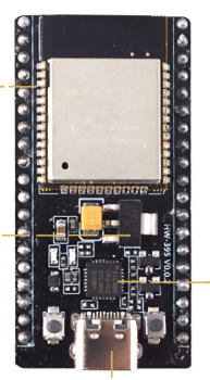
 Design with ESP32-Wroom-32 in Cirkit Designer
Introduction
The ESP32-Wroom-32 is a powerful, low-cost Wi-Fi and Bluetooth microcontroller module with a dual-core processor, making it an ideal choice for a wide range of IoT applications. This versatile module is designed to provide robust connectivity and high performance, enabling developers to create innovative and efficient solutions for smart devices, home automation, industrial automation, and more.
Explore Projects Built with ESP32-Wroom-32
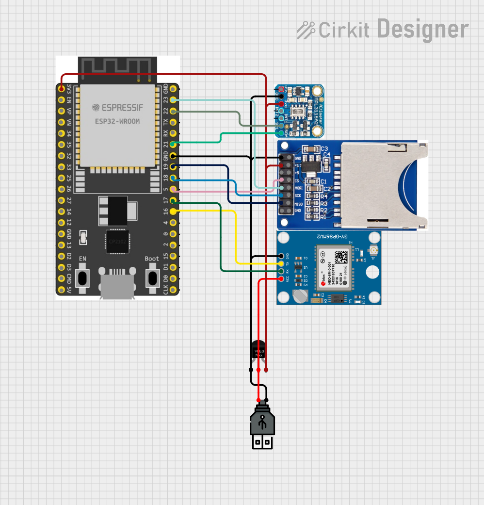
 Open Project in Cirkit Designer
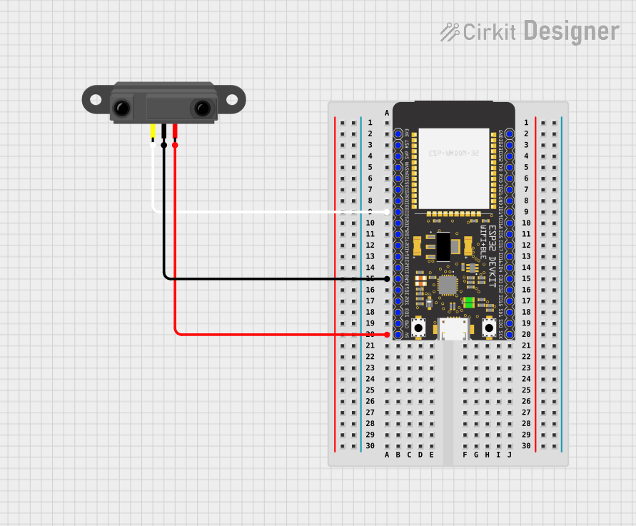
 Open Project in Cirkit Designer
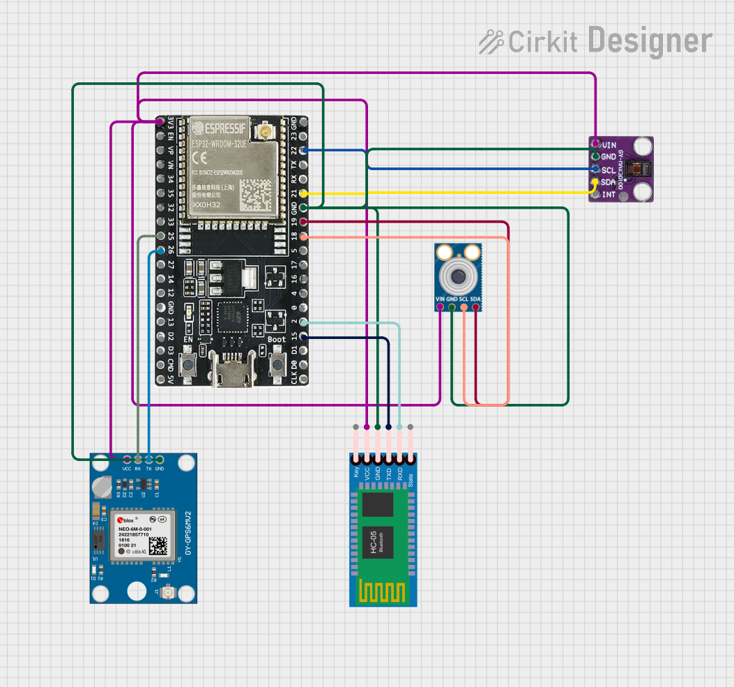
 Open Project in Cirkit Designer
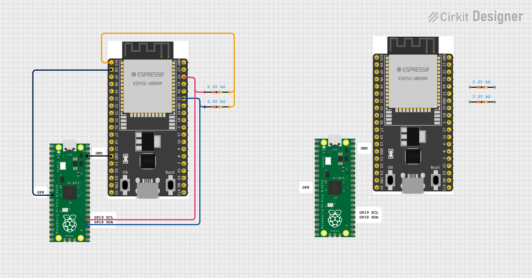
 Open Project in Cirkit Designer
Explore Projects Built with ESP32-Wroom-32

 Open Project in Cirkit Designer
 Open Project in Cirkit Designer
 Open Project in Cirkit Designer
 Open Project in Cirkit Designer
Technical Specifications
Key Technical Details
| Parameter | Value |
|---|---|
| Microcontroller | Tensilica Xtensa LX6 dual-core processor |
| Clock Speed | Up to 240 MHz |
| Flash Memory | 4 MB |
| SRAM | 520 KB |
| Wi-Fi Standards | 802.11 b/g/n |
| Bluetooth | v4.2 BR/EDR and BLE |
| Operating Voltage | 3.0V to 3.6V |
| I/O Pins | 34 GPIO pins |
| ADC Channels | 18 (12-bit ADC) |
| DAC Channels | 2 (8-bit DAC) |
| Communication | UART, SPI, I2C, I2S, CAN, Ethernet, PWM |
| Power Consumption | 5 µA (deep sleep), 10 mA (light sleep), |
| 240 mA (active mode) |
Pin Configuration and Descriptions
| Pin Number | Pin Name | Description |
|---|---|---|
| 1 | EN | Module enable pin |
| 2 | IO0 | GPIO0, used for boot mode selection |
| 3 | IO1 | GPIO1, UART0 TXD |
| 4 | IO2 | GPIO2, ADC2_CH2, HSPI_CLK |
| 5 | IO3 | GPIO3, UART0 RXD |
| 6 | IO4 | GPIO4, ADC2_CH0, HSPI_HD |
| 7 | IO5 | GPIO5, ADC2_CH1, HSPI_CS0 |
| 8 | IO6 | GPIO6, Flash SCK |
| 9 | IO7 | GPIO7, Flash SD0 |
| 10 | IO8 | GPIO8, Flash SD1 |
| 11 | IO9 | GPIO9, Flash SD2 |
| 12 | IO10 | GPIO10, Flash SD3 |
| 13 | IO11 | GPIO11, Flash CMD |
| 14 | IO12 | GPIO12, ADC2_CH5, HSPI_Q |
| 15 | IO13 | GPIO13, ADC2_CH4, HSPI_WP |
| 16 | IO14 | GPIO14, ADC2_CH6, HSPI_CLK |
| 17 | IO15 | GPIO15, ADC2_CH3, HSPI_CS0 |
| 18 | IO16 | GPIO16, UART2 RXD |
| 19 | IO17 | GPIO17, UART2 TXD |
| 20 | IO18 | GPIO18, VSPI_CLK |
| 21 | IO19 | GPIO19, VSPI_Q |
| 22 | IO21 | GPIO21, I2C SDA |
| 23 | IO22 | GPIO22, I2C SCL |
| 24 | IO23 | GPIO23, VSPI_D |
| 25 | IO25 | GPIO25, DAC1, ADC2_CH8 |
| 26 | IO26 | GPIO26, DAC2, ADC2_CH9 |
| 27 | IO27 | GPIO27, ADC2_CH7 |
| 28 | IO32 | GPIO32, ADC1_CH4, TOUCH9 |
| 29 | IO33 | GPIO33, ADC1_CH5, TOUCH8 |
| 30 | IO34 | GPIO34, ADC1_CH6 |
| 31 | IO35 | GPIO35, ADC1_CH7 |
| 32 | IO36 | GPIO36, ADC1_CH0, SENS_VP |
| 33 | IO39 | GPIO39, ADC1_CH3, SENS_VN |
Usage Instructions
How to Use the ESP32-Wroom-32 in a Circuit
- Power Supply: Ensure the module is powered with a stable voltage between 3.0V and 3.6V. The recommended voltage is 3.3V.
- Boot Mode Selection: Connect GPIO0 to GND to enter the bootloader mode for programming. For normal operation, GPIO0 should be pulled high.
- Connecting to Peripherals: Use the GPIO pins to connect sensors, actuators, and other peripherals. Refer to the pin configuration table for specific pin functions.
- Programming: The ESP32-Wroom-32 can be programmed using the Arduino IDE or the ESP-IDF (Espressif IoT Development Framework). Ensure the correct board and port are selected in the IDE.
Important Considerations and Best Practices
- Power Supply: Use a low-noise power supply to avoid interference with the Wi-Fi and Bluetooth signals.
- GPIO Voltage Levels: The GPIO pins are not 5V tolerant. Ensure all connected devices operate at 3.3V logic levels.
- Antenna Placement: For optimal Wi-Fi and Bluetooth performance, ensure the antenna area is free from obstructions and placed away from metal objects.
- Heat Dissipation: The module can get warm during operation. Ensure adequate ventilation or heat sinking if used in a confined space.
Example Code for Arduino UNO
#include <WiFi.h>

// Replace with your network credentials
const char* ssid = "your_SSID";
const char* password = "your_PASSWORD";

void setup() {
  // Initialize serial communication
  Serial.begin(115200);

  // Connect to Wi-Fi
  WiFi.begin(ssid, password);

  // Wait for connection
  while (WiFi.status() != WL_CONNECTED) {
    delay(1000);
    Serial.println("Connecting to WiFi...");
  }

  // Print the IP address
  Serial.println("Connected to WiFi");
  Serial.print("IP Address: ");
  Serial.println(WiFi.localIP());
}

void loop() {
  // Put your main code here, to run repeatedly
}
Troubleshooting and FAQs
Common Issues Users Might Face
- Wi-Fi Connection Issues: The module may fail to connect to Wi-Fi due to incorrect credentials, weak signal, or interference.
- Programming Errors: Errors during programming can occur due to incorrect boot mode selection or faulty USB connections.
- Overheating: The module may overheat if used in a poorly ventilated area or with high power consumption peripherals.
Solutions and Tips for Troubleshooting
- Wi-Fi Connection Issues: Double-check the SSID and password. Ensure the module is within range of the Wi-Fi router and there are no significant sources of interference nearby.
- Programming Errors: Ensure GPIO0 is connected to GND during programming. Check the USB cable and port for any faults. Use a reliable power source.
- Overheating: Improve ventilation around the module. Use heat sinks if necessary. Reduce the power consumption of connected peripherals.
FAQs
Q: Can the ESP32-Wroom-32 be powered with 5V? A: No, the module should be powered with a voltage between 3.0V and 3.6V. The recommended voltage is 3.3V.
Q: How do I reset the ESP32-Wroom-32? A: You can reset the module by pulling the EN pin low momentarily.
Q: Can I use the ESP32-Wroom-32 with the Arduino IDE? A: Yes, the ESP32-Wroom-32 is compatible with the Arduino IDE. You need to install the ESP32 board support package in the Arduino IDE.
Q: How do I enter the bootloader mode for programming? A: Connect GPIO0 to GND and then reset the module to enter the bootloader mode.
Q: Is the ESP32-Wroom-32 suitable for battery-powered applications? A: Yes, the module has low power consumption modes (deep sleep and light sleep) that make it suitable for battery-powered applications.
This documentation provides a comprehensive guide to using the ESP32-Wroom-32 module. Whether you are a beginner or an experienced user, this guide will help you get the most out of this powerful microcontroller module.