How to Use bc547: Examples, Pinouts, and Specs
Introduction
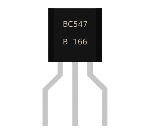
The BC547 transistor is a widely used NPN bipolar junction transistor (BJT) known for its reliability and versatility. It is commonly employed in general-purpose amplification and switching applications. Due to its low noise and high current gain characteristics, the BC547 is suitable for a multitude of electronic projects, ranging from simple DIY circuits to more complex designs.
Explore Projects Built with bc547
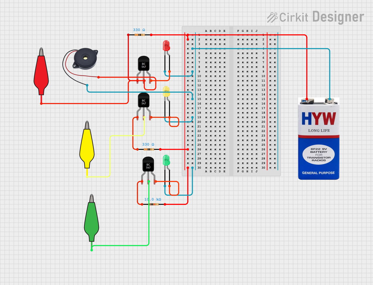
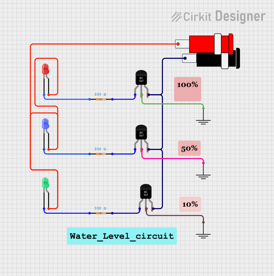
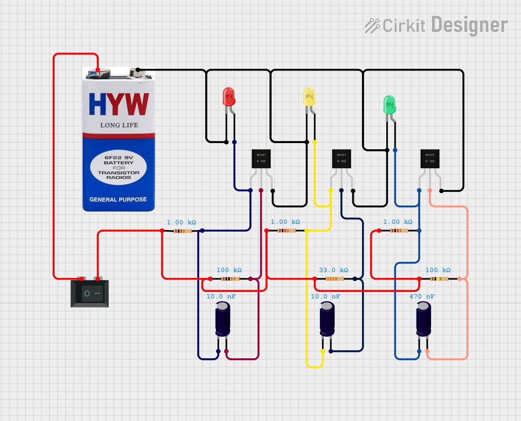
Explore Projects Built with bc547
Common Applications and Use Cases
- Signal amplification in audio devices
- Switching operations in embedded systems
- Driver stages in amplifiers
- Oscillator circuits
- Digital logic circuits
Technical Specifications
Key Technical Details
- Type: NPN
- Collector-Emitter Voltage (Vce): 45V maximum
- Collector-Base Voltage (Vcb): 50V maximum
- Emitter-Base Voltage (Veb): 6V maximum
- Collector Current (Ic): 100mA maximum
- DC Current Gain (hFE): 110 to 800 (varies with Ic)
- Transition Frequency (fT): 300MHz typical
- Power Dissipation (Pd): 625mW maximum
Pin Configuration and Descriptions
| Pin Number | Name | Description |
|---|---|---|
| 1 | Emitter (E) | Emits electrons into the base; must be connected to ground in NPN transistors |
| 2 | Base (B) | Controls the transistor's operation; small current to base allows a larger current to flow from the collector to the emitter |
| 3 | Collector (C) | Collects electrons from the emitter; connected to the load and positive voltage |
Usage Instructions
How to Use the BC547 in a Circuit
- Biasing the Transistor: Ensure that the base-emitter junction is forward-biased and the collector-base junction is reverse-biased.
- Base Resistor Selection: Choose a base resistor to limit the current into the base, thus protecting the transistor from overcurrent.
- Load Connection: Connect the load to the collector, ensuring that the maximum current and voltage ratings are not exceeded.
- Emitter Grounding: Connect the emitter to the ground of the circuit.
Important Considerations and Best Practices
- Always check the pinout of the BC547 before connecting it to your circuit.
- Do not exceed the maximum voltage and current ratings to prevent damage.
- Use a current-limiting resistor with the base to prevent excessive base current.
- Consider heat sinking if operating near maximum power dissipation.
- When switching inductive loads, use a flyback diode to protect the transistor from voltage spikes.
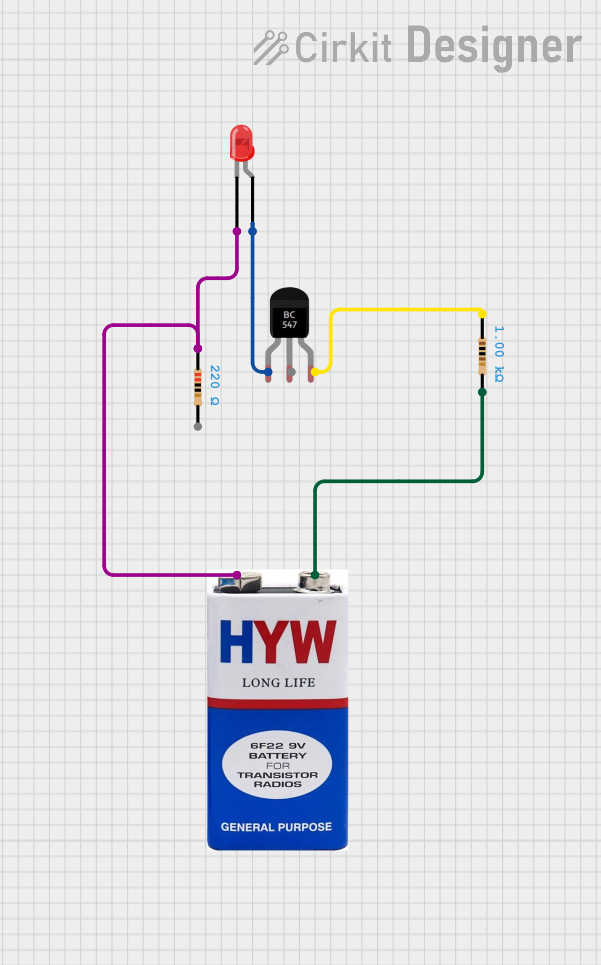
Example Circuit: Using BC547 with Arduino UNO
// Example code to use BC547 for switching an LED with Arduino UNO

const int ledPin = 13; // LED connected to digital pin 13
const int transistorPin = 2; // Base of BC547 connected to digital pin 2

void setup() {
  pinMode(ledPin, OUTPUT); // Set the LED pin as output
  pinMode(transistorPin, OUTPUT); // Set the transistor pin as output
}

void loop() {
  digitalWrite(transistorPin, HIGH); // Turn on the transistor
  delay(1000); // Wait for 1 second
  digitalWrite(transistorPin, LOW); // Turn off the transistor
  delay(1000); // Wait for 1 second
}
Troubleshooting and FAQs
Common Issues
- Transistor Not Switching: Check if the base-emitter junction is properly biased and the base resistor is of the correct value.
- Excessive Heat: Ensure the transistor is not operating above its maximum power dissipation.
- Unexpected Operation: Verify the pinout and ensure that the collector and emitter are not reversed.
Solutions and Tips for Troubleshooting
- Use a multimeter to check for proper voltage levels at the base, collector, and emitter.
- Inspect the circuit for any solder bridges or shorts that may affect the transistor's operation.
- If the transistor is suspected to be faulty, replace it with a new one and retest the circuit.
FAQs
Q: Can I use the BC547 to switch AC loads? A: No, the BC547 is designed for DC applications only.
Q: What can I do if the BC547 is getting too hot? A: Check if the current through the collector is within the specified limit and consider using a heat sink.
Q: How can I increase the current gain of my circuit? A: The current gain is a property of the transistor. To effectively increase the current in your circuit, you may consider using a Darlington pair configuration.
Q: Is there a PNP equivalent of the BC547? A: Yes, the BC557 is a commonly used PNP equivalent of the BC547.
This documentation provides a comprehensive guide to using the BC547 NPN transistor in various electronic applications. Always ensure that you are working within the specified limits of the component to achieve the best performance and reliability.