How to Use KY-022: Examples, Pinouts, and Specs
Introduction
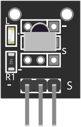
The KY-022 is an infrared (IR) receiver module designed to detect and process infrared signals, typically from remote controls. It is a compact and reliable component that enables wireless communication between a remote control and a device. The module is widely used in projects involving home automation, robotics, and consumer electronics, where remote control functionality is required.
Explore Projects Built with KY-022


Explore Projects Built with KY-022
Common Applications:
- Remote-controlled robots and vehicles
- Home automation systems
- Media player control
- Wireless communication in IoT devices
- Learning and prototyping with Arduino and other microcontrollers
Technical Specifications
The KY-022 module is built around a 38 kHz IR receiver, which is tuned to detect signals from most standard remote controls. Below are the key technical details:
| Parameter | Value |
|---|---|
| Operating Voltage | 3.0V to 5.5V |
| Operating Current | 0.4mA to 1.5mA |
| Carrier Frequency | 38 kHz |
| Reception Distance | Up to 18 meters (line of sight) |
| Viewing Angle | ±45° |
| Output Signal | Digital (active low) |
| Dimensions | 18.5mm x 15mm x 10mm |
Pin Configuration:
The KY-022 module has three pins, as described in the table below:
| Pin | Name | Description |
|---|---|---|
| 1 | Signal | Digital output pin that transmits the received IR signal (active low) |
| 2 | VCC | Power supply pin (3.0V to 5.5V) |
| 3 | GND | Ground pin for the module |
Usage Instructions
The KY-022 module is straightforward to use and can be easily interfaced with microcontrollers like Arduino. Below are the steps to use the module in a circuit:
Connecting the KY-022:
- Power the Module: Connect the
VCCpin to a 5V power source and theGNDpin to the ground. - Signal Output: Connect the
Signalpin to a digital input pin on your microcontroller (e.g., Arduino). - Place the Module: Ensure the module's IR receiver is facing the remote control for optimal signal reception.
Arduino Example Code:
The following example demonstrates how to use the KY-022 with an Arduino UNO to decode IR signals from a remote control. This code uses the IRremote library, which must be installed in the Arduino IDE.
#include <IRremote.h> // Include the IRremote library

const int RECV_PIN = 2; // Define the pin connected to the KY-022 Signal pin
IRrecv irrecv(RECV_PIN); // Create an IR receiver object
decode_results results;  // Variable to store decoded IR data

void setup() {
  Serial.begin(9600); // Initialize serial communication for debugging
  irrecv.enableIRIn(); // Start the IR receiver
  Serial.println("KY-022 IR Receiver is ready to decode signals.");
}

void loop() {
  if (irrecv.decode(&results)) { // Check if an IR signal is received
    Serial.print("Received IR code: ");
    Serial.println(results.value, HEX); // Print the received code in hexadecimal
    irrecv.resume(); // Prepare to receive the next signal
  }
}
Important Considerations:
- Line of Sight: Ensure there is a clear line of sight between the remote control and the KY-022 for reliable signal reception.
- Ambient Light: Avoid using the module in environments with strong IR interference, such as direct sunlight or near incandescent bulbs.
- Power Supply: Use a stable power source to prevent erratic behavior.
Troubleshooting and FAQs
Common Issues and Solutions:
No Signal Detected:
- Ensure the remote control is functional and emits IR signals.
- Verify the connections (VCC, GND, and Signal) are correct and secure.
- Check that the module is powered within the specified voltage range.
Unstable or Incorrect Signal:
- Reduce ambient IR interference by shielding the module from strong light sources.
- Ensure the remote control is within the module's reception range and angle.
Arduino Not Receiving Data:
- Confirm that the
IRremotelibrary is installed and properly included in the code. - Verify that the correct digital pin is defined in the code (
RECV_PIN).
- Confirm that the
FAQs:
Q: Can the KY-022 receive signals from any remote control?
A: The KY-022 is designed to work with most remote controls that use a 38 kHz carrier frequency, which is standard for many consumer devices.
Q: How can I test if the KY-022 is working?
A: Use a smartphone camera to check if the remote control emits IR light when a button is pressed. Then, connect the KY-022 to an Arduino and run the example code to verify signal reception.
Q: Can I use the KY-022 with a Raspberry Pi?
A: Yes, the KY-022 can be used with a Raspberry Pi. You will need to use an appropriate library, such as lirc, to decode the IR signals.
By following this documentation, you can effectively integrate the KY-022 into your projects and troubleshoot any issues that arise.