How to Use MAX30100: Examples, Pinouts, and Specs
Introduction
The MAX30100 is a pulse oximeter and heart-rate monitor sensor that uses photoplethysmography (PPG) to measure blood oxygen levels (SpO2) and heart rate. It integrates two LEDs (red and infrared) and a photodetector in a compact package, along with an analog-to-digital converter (ADC) and a digital signal processor (DSP) for accurate measurements. The MAX30100 is designed for low-power operation, making it ideal for wearable health monitoring devices such as fitness trackers, smartwatches, and medical equipment.
Explore Projects Built with MAX30100


Explore Projects Built with MAX30100
Common Applications and Use Cases
- Wearable fitness trackers and smartwatches
- Medical devices for SpO2 and heart rate monitoring
- Health monitoring systems for athletes
- Research and development in biomedical engineering
- IoT-based health monitoring solutions
Technical Specifications
The MAX30100 is a highly integrated sensor with the following key specifications:
| Parameter | Value |
|---|---|
| Operating Voltage | 1.8V (core) and 3.3V (I/O) |
| Operating Current | 0.7mA (typical, during measurement) |
| Standby Current | 0.7µA |
| Measurement Range | SpO2: 70% to 100%, Heart Rate: 30-240 bpm |
| Communication Interface | I2C |
| I2C Address | 0x57 (default) |
| LED Wavelengths | Red: 660nm, Infrared: 880nm |
| Sampling Rate | Programmable: 50Hz to 1000Hz |
| Package | 14-pin optical module |
| Operating Temperature | -40°C to +85°C |
Pin Configuration and Descriptions
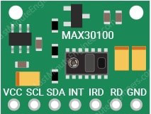
The MAX30100 has 14 pins, but only a subset is typically used in most applications. Below is the pin configuration:
| Pin Number | Pin Name | Description |
|---|---|---|
| 1 | VIN | Power supply input (1.8V to 3.3V) |
| 2 | GND | Ground |
| 3 | SDA | I2C data line |
| 4 | SCL | I2C clock line |
| 5 | INT | Interrupt output (active low) |
| 6-14 | NC | Not connected |
Usage Instructions
How to Use the MAX30100 in a Circuit
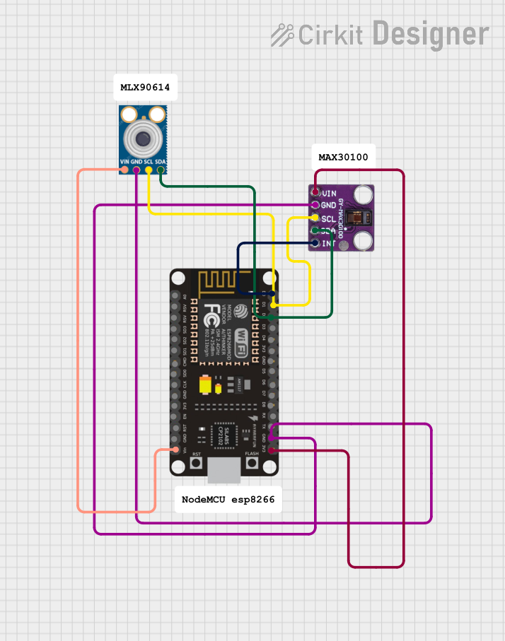
- Power Supply: Connect the VIN pin to a 3.3V power source and the GND pin to ground.
- I2C Communication: Connect the SDA and SCL pins to the corresponding I2C pins on your microcontroller (e.g., Arduino UNO). Use pull-up resistors (typically 4.7kΩ) on both SDA and SCL lines.
- Interrupt Pin: Optionally, connect the INT pin to a GPIO pin on your microcontroller to handle interrupts.
- Bypass Capacitor: Place a 0.1µF capacitor between VIN and GND for power supply decoupling.
Important Considerations and Best Practices
- Ensure proper alignment of the sensor with the skin for accurate readings.
- Avoid ambient light interference by enclosing the sensor in a dark housing.
- Use a low-noise power supply to minimize measurement errors.
- Calibrate the sensor for your specific application to improve accuracy.
Example Code for Arduino UNO
Below is an example of how to interface the MAX30100 with an Arduino UNO using the MAX30100 library:
#include <Wire.h>
#include "MAX30100_PulseOximeter.h"

// Create an instance of the PulseOximeter class
PulseOximeter pox;

// Timer variables for periodic updates
uint32_t lastUpdate = 0;

// Callback function for new heart rate and SpO2 readings
void onBeatDetected() {
  Serial.println("Beat detected!");
}

void setup() {
  Serial.begin(9600); // Initialize serial communication
  Serial.println("Initializing MAX30100...");

  // Initialize the MAX30100 sensor
  if (!pox.begin()) {
    Serial.println("Failed to initialize MAX30100. Check connections!");
    while (1);
  }

  // Set the callback function for beat detection
  pox.setOnBeatDetectedCallback(onBeatDetected);

  Serial.println("MAX30100 initialized successfully.");
}

void loop() {
  // Update the sensor readings
  pox.update();

  // Print heart rate and SpO2 every second
  if (millis() - lastUpdate > 1000) {
    lastUpdate = millis();
    Serial.print("Heart Rate: ");
    Serial.print(pox.getHeartRate());
    Serial.print(" bpm, SpO2: ");
    Serial.print(pox.getSpO2());
    Serial.println(" %");
  }
}
Notes:
- Install the
MAX30100_PulseOximeterlibrary from the Arduino Library Manager before running the code. - Ensure the I2C address (0x57) matches the default address of the MAX30100.
Troubleshooting and FAQs
Common Issues and Solutions
No Response from the Sensor
- Cause: Incorrect wiring or power supply.
- Solution: Double-check the connections and ensure the VIN pin is connected to 3.3V.
Inaccurate Readings
- Cause: Ambient light interference or poor skin contact.
- Solution: Shield the sensor from ambient light and ensure proper alignment with the skin.
I2C Communication Failure
- Cause: Missing pull-up resistors or incorrect I2C address.
- Solution: Add 4.7kΩ pull-up resistors to SDA and SCL lines and verify the I2C address.
Sensor Overheating
- Cause: Continuous operation of LEDs at high current.
- Solution: Use the lowest LED current settings that provide reliable readings.
FAQs
Q1: Can the MAX30100 measure SpO2 and heart rate simultaneously?
A1: Yes, the MAX30100 is designed to measure both SpO2 and heart rate simultaneously using its dual LED and photodetector setup.
Q2: What is the maximum distance between the sensor and the microcontroller?
A2: The maximum distance depends on the I2C bus capacitance. For reliable communication, keep the distance under 1 meter and use proper pull-up resistors.
Q3: Can the MAX30100 be used with a 5V microcontroller?
A3: Yes, but you must use a level shifter for the I2C lines, as the MAX30100 operates at 3.3V logic levels.
Q4: How do I improve measurement accuracy?
A4: Minimize ambient light interference, ensure good skin contact, and calibrate the sensor for your specific application.
This concludes the documentation for the MAX30100.