How to Use ESP32-C3 Super Mini: Examples, Pinouts, and Specs
Introduction
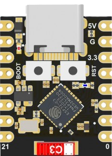
The ESP32-C3 Super Mini, manufactured by Espressif, is a compact and powerful microcontroller designed for IoT (Internet of Things) applications. It features integrated Wi-Fi and Bluetooth Low Energy (BLE) connectivity, making it ideal for wireless communication in smart devices. With its low power consumption and high performance, the ESP32-C3 Super Mini is well-suited for battery-powered devices, home automation, wearables, and industrial IoT systems.
Explore Projects Built with ESP32-C3 Super Mini


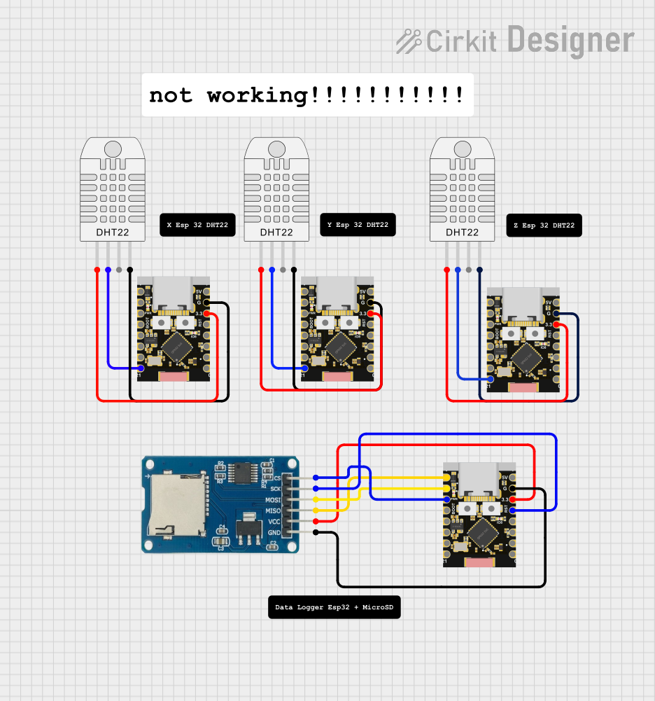
Explore Projects Built with ESP32-C3 Super Mini
Common Applications
- Smart home devices (e.g., smart plugs, lights, and sensors)
- Wearable electronics
- Industrial IoT systems
- Wireless data logging and monitoring
- Low-power wireless communication systems
Technical Specifications
The ESP32-C3 Super Mini is based on the ESP32-C3 chip, which is a RISC-V-based microcontroller. Below are its key technical details:
Key Features
- Processor: 32-bit RISC-V single-core processor, up to 160 MHz
- Memory: 400 KB SRAM, 384 KB ROM, 4 MB Flash
- Connectivity:
- Wi-Fi: 802.11 b/g/n (2.4 GHz)
- Bluetooth: BLE 5.0
- GPIO Pins: 15 programmable GPIOs
- Operating Voltage: 3.3V
- Power Consumption:
- Deep Sleep: ~5 µA
- Active Mode: ~75 mA (typical)
- Interfaces:
- UART, SPI, I2C, I2S, PWM, ADC
- Dimensions: 10 mm x 10 mm (approx.)
- Operating Temperature: -40°C to +85°C
Pin Configuration
The ESP32-C3 Super Mini has a compact pinout. Below is the pin configuration:
| Pin Number | Pin Name | Description |
|---|---|---|
| 1 | GND | Ground |
| 2 | 3V3 | 3.3V Power Supply |
| 3 | GPIO0 | General Purpose I/O, Boot Mode Pin |
| 4 | GPIO1 | General Purpose I/O |
| 5 | GPIO2 | General Purpose I/O |
| 6 | GPIO3 | General Purpose I/O |
| 7 | GPIO4 | General Purpose I/O |
| 8 | GPIO5 | General Purpose I/O |
| 9 | RXD | UART Receive |
| 10 | TXD | UART Transmit |
| 11 | ADC1 | Analog-to-Digital Converter Input |
| 12 | EN | Enable Pin (Active High) |
| 13 | RST | Reset Pin |
| 14 | SDA | I2C Data Line |
| 15 | SCL | I2C Clock Line |
Usage Instructions
Using the ESP32-C3 Super Mini in a Circuit
- Power Supply: Provide a stable 3.3V power supply to the
3V3pin and connect theGNDpin to ground. - Boot Mode: To upload code, connect
GPIO0to ground during reset. After uploading, disconnectGPIO0from ground. - Programming: Use a USB-to-UART adapter to connect the
RXDandTXDpins to your computer for programming. - Peripherals: Connect sensors, actuators, or other peripherals to the GPIO pins. Use the ADC pin for analog inputs and the I2C pins (
SDAandSCL) for I2C communication.
Important Considerations
- Voltage Levels: Ensure all connected peripherals operate at 3.3V logic levels to avoid damaging the microcontroller.
- Heat Management: While the ESP32-C3 Super Mini is efficient, ensure proper ventilation if used in high-temperature environments.
- Deep Sleep Mode: Use deep sleep mode to minimize power consumption in battery-powered applications.
Example Code for Arduino UNO Integration
The ESP32-C3 Super Mini can be programmed using the Arduino IDE. Below is an example of how to blink an LED connected to GPIO2:
// Example: Blink an LED connected to GPIO2 on the ESP32-C3 Super Mini

// Define the GPIO pin for the LED
#define LED_PIN 2

void setup() {
  // Initialize the LED pin as an output
  pinMode(LED_PIN, OUTPUT);
}

void loop() {
  // Turn the LED on
  digitalWrite(LED_PIN, HIGH);
  delay(1000); // Wait for 1 second

  // Turn the LED off
  digitalWrite(LED_PIN, LOW);
  delay(1000); // Wait for 1 second
}
Troubleshooting and FAQs
Common Issues
The ESP32-C3 Super Mini is not detected by the computer:
- Ensure the USB-to-UART adapter is properly connected.
- Check that the correct COM port is selected in the Arduino IDE.
- Verify that the correct board and upload settings are selected in the IDE.
Code upload fails:
- Ensure
GPIO0is connected to ground during the reset process. - Check the USB cable for data transfer capability (some cables are power-only).
- Ensure
Wi-Fi or Bluetooth is not working:
- Verify that the correct credentials or pairing settings are used in your code.
- Ensure the device is within range of the Wi-Fi router or Bluetooth device.
Tips for Troubleshooting
- Use a multimeter to check the voltage levels on the
3V3andGNDpins. - Monitor the serial output in the Arduino IDE for error messages or debugging information.
- Update the ESP32 board package in the Arduino IDE to the latest version.
By following this documentation, you can effectively integrate and utilize the ESP32-C3 Super Mini in your IoT projects.