
How to Use SparkFun Thumb Joystick Breakout: Examples, Pinouts, and Specs
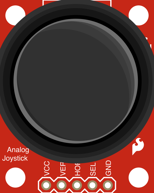
 Design with SparkFun Thumb Joystick Breakout in Cirkit Designer
Introduction
The SparkFun Thumb Joystick Breakout (Manufacturer Part ID: BOB-09110) is a compact joystick module designed for intuitive control of movement in two dimensions (X and Y axes). It features a thumb-operated joystick with a built-in push button, making it an excellent choice for applications requiring precise directional input. This breakout board is widely used in robotics, gaming controllers, remote control devices, and other interactive projects.
The module is easy to integrate into microcontroller-based systems, such as Arduino, and provides both analog and digital outputs for versatile functionality.
Explore Projects Built with SparkFun Thumb Joystick Breakout
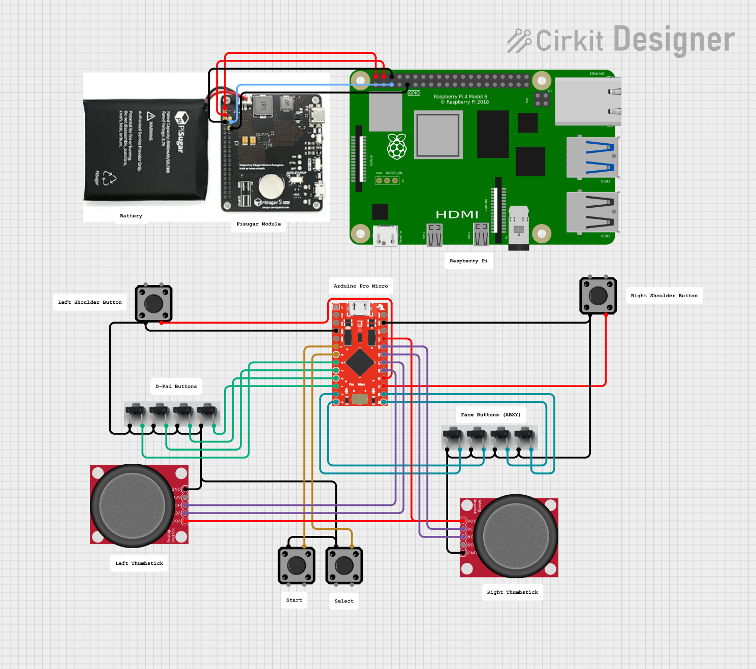 Open Project in Cirkit Designer
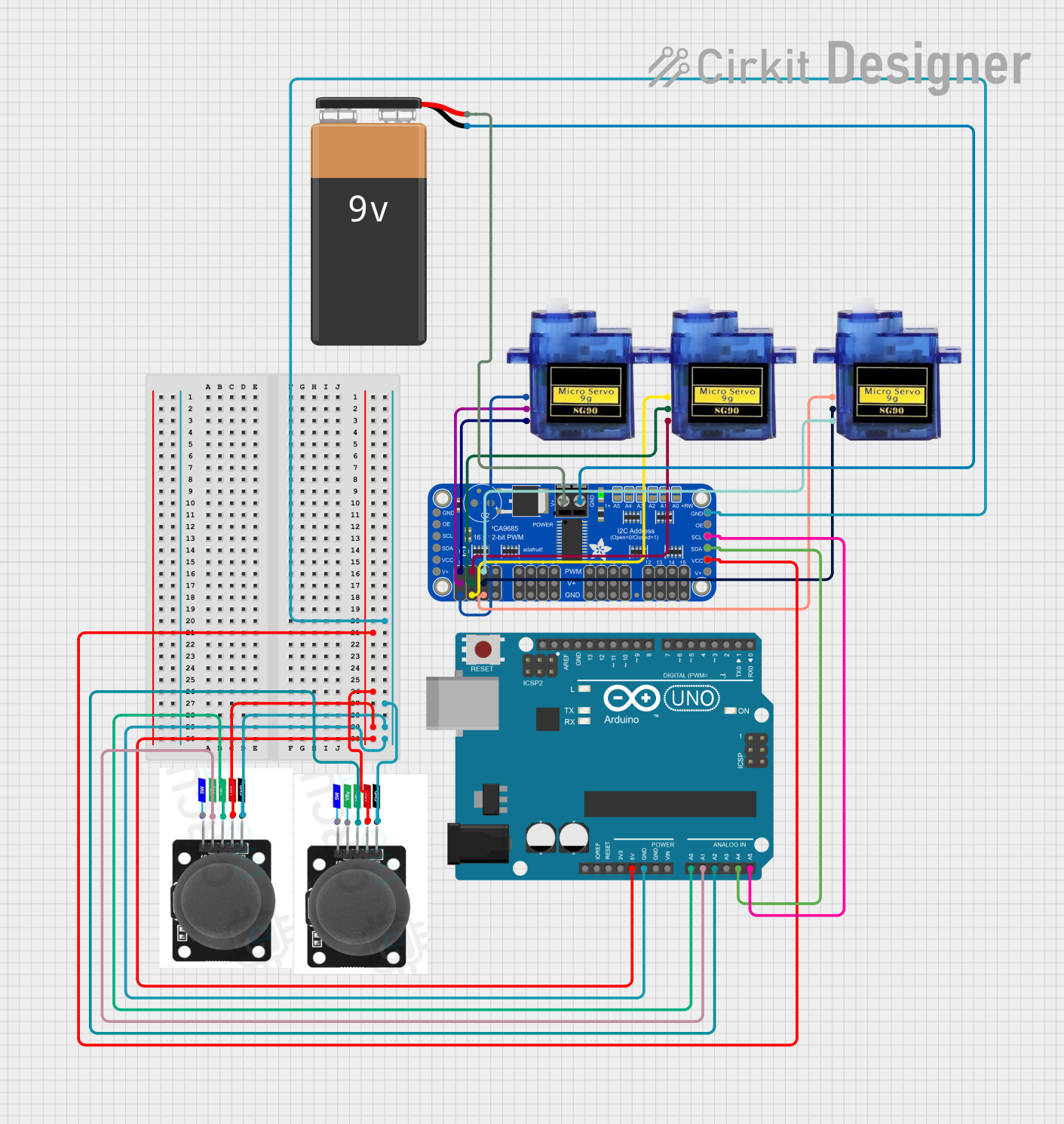 Open Project in Cirkit Designer
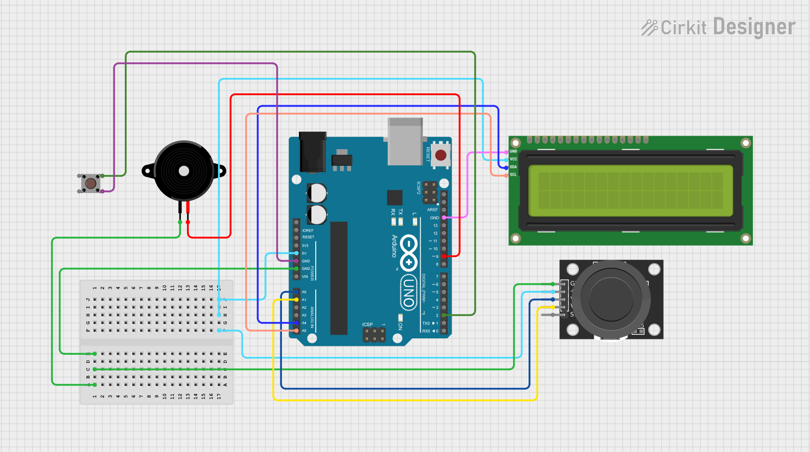 Open Project in Cirkit Designer
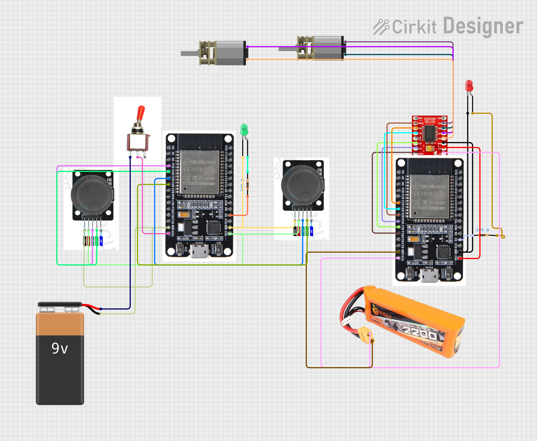 Open Project in Cirkit Designer
Explore Projects Built with SparkFun Thumb Joystick Breakout
Open Project in Cirkit DesignerOpen Project in Cirkit DesignerOpen Project in Cirkit DesignerOpen Project in Cirkit DesignerTechnical Specifications
Below are the key technical details of the SparkFun Thumb Joystick Breakout:
- Manufacturer: SparkFun Electronics
- Part Number: BOB-09110
- Operating Voltage: 3.3V to 5V
- Output Type: Analog (X and Y axes), Digital (push button)
- Joystick Movement Range: ±200 kΩ potentiometer for X and Y axes
- Push Button Type: Momentary, normally open
- Dimensions: 26.5mm x 26.5mm (1.04" x 1.04")
- Mounting Holes: 2 x 2.0mm diameter
Pin Configuration and Descriptions
The SparkFun Thumb Joystick Breakout has a 5-pin header for easy connection. The pinout is as follows:
| Pin | Name | Description |
|---|---|---|
| 1 | GND | Ground connection for the module. |
| 2 | VCC | Power supply input (3.3V to 5V). |
| 3 | VRx | Analog output for the X-axis position. |
| 4 | VRy | Analog output for the Y-axis position. |
| 5 | SW | Digital output for the push button (active LOW when pressed, HIGH when released). |
Usage Instructions
How to Use the Component in a Circuit
Powering the Module:
Connect theVCCpin to a 3.3V or 5V power source and theGNDpin to the ground of your circuit.Reading Joystick Position:
- The
VRxandVRypins output analog voltages corresponding to the joystick's position along the X and Y axes, respectively. - These voltages can be read using the analog input pins of a microcontroller (e.g., Arduino).
- The
Using the Push Button:
- The
SWpin outputs a digital signal. It is HIGH when the button is not pressed and LOW when pressed. - Connect this pin to a digital input pin on your microcontroller and use a pull-up resistor if necessary.
- The
Example Arduino UNO Code
Below is an example code snippet for interfacing the SparkFun Thumb Joystick Breakout with an Arduino UNO:
// Define pin connections
const int VRxPin = A0; // X-axis connected to analog pin A0
const int VRyPin = A1; // Y-axis connected to analog pin A1
const int SWPin = 2;   // Push button connected to digital pin 2

void setup() {
  // Initialize serial communication for debugging
  Serial.begin(9600);

  // Configure the push button pin as input with internal pull-up resistor
  pinMode(SWPin, INPUT_PULLUP);
}

void loop() {
  // Read the X and Y axis values (0 to 1023)
  int xValue = analogRead(VRxPin);
  int yValue = analogRead(VRyPin);

  // Read the push button state (LOW when pressed, HIGH when released)
  int buttonState = digitalRead(SWPin);

  // Print the joystick values to the Serial Monitor
  Serial.print("X: ");
  Serial.print(xValue);
  Serial.print(" | Y: ");
  Serial.print(yValue);
  Serial.print(" | Button: ");
  Serial.println(buttonState == LOW ? "Pressed" : "Released");

  // Add a small delay for stability
  delay(100);
}
Important Considerations and Best Practices
- Ensure the power supply voltage matches the module's operating range (3.3V to 5V).
- Use decoupling capacitors near the power pins to reduce noise in analog readings.
- Avoid applying excessive force to the joystick to prevent damage.
- If the joystick readings are noisy, consider adding software filtering or averaging in your code.
Troubleshooting and FAQs
Common Issues and Solutions
No Output from the Joystick:
- Cause: Incorrect wiring or loose connections.
- Solution: Double-check all connections, ensuring the
VCCandGNDpins are properly connected.
Analog Readings Are Unstable:
- Cause: Electrical noise or insufficient power supply decoupling.
- Solution: Add a 0.1µF ceramic capacitor between
VCCandGNDnear the module.
Push Button Not Responding:
- Cause: Missing pull-up resistor or incorrect pin configuration.
- Solution: Use the
INPUT_PULLUPmode in your microcontroller code or add an external pull-up resistor.
Joystick Values Are Not Centered:
- Cause: Manufacturing tolerances or mechanical wear.
- Solution: Calibrate the joystick in software by mapping the raw analog values to a centered range.
FAQs
Q1: Can I use this module with a Raspberry Pi?
A1: Yes, the module can be used with a Raspberry Pi. Connect the analog outputs (VRx and VRy) to an external ADC (Analog-to-Digital Converter) since the Raspberry Pi lacks built-in ADC functionality.
Q2: What is the expected analog output range?
A2: The VRx and VRy pins typically output a voltage range from 0V to the supply voltage (3.3V or 5V), depending on the joystick's position.
Q3: Is the push button debounce handled by the module?
A3: No, the module does not include hardware debounce for the push button. You can implement software debounce in your microcontroller code if needed.
Q4: Can I replace the joystick with a different one?
A4: The breakout board is designed for the included joystick. Replacing it may require modifications to the board or connections.
By following this documentation, you can effectively integrate the SparkFun Thumb Joystick Breakout into your projects and troubleshoot common issues with ease.