How to Use High Power 265-nm COB UV-C LED: Examples, Pinouts, and Specs

Introduction
The High Power 265-nm COB UV-C LED (Manufacturer Part ID: VC2X2C48L6-265-V1) by Violumas is a high-intensity light-emitting diode designed to emit ultraviolet light at a wavelength of 265 nanometers. This wavelength is particularly effective for sterilization and disinfection applications, as it disrupts the DNA and RNA of microorganisms, rendering them inactive. The component is built using Chip-on-Board (COB) technology, ensuring high power density and efficient thermal management.
Explore Projects Built with High Power 265-nm COB UV-C LED
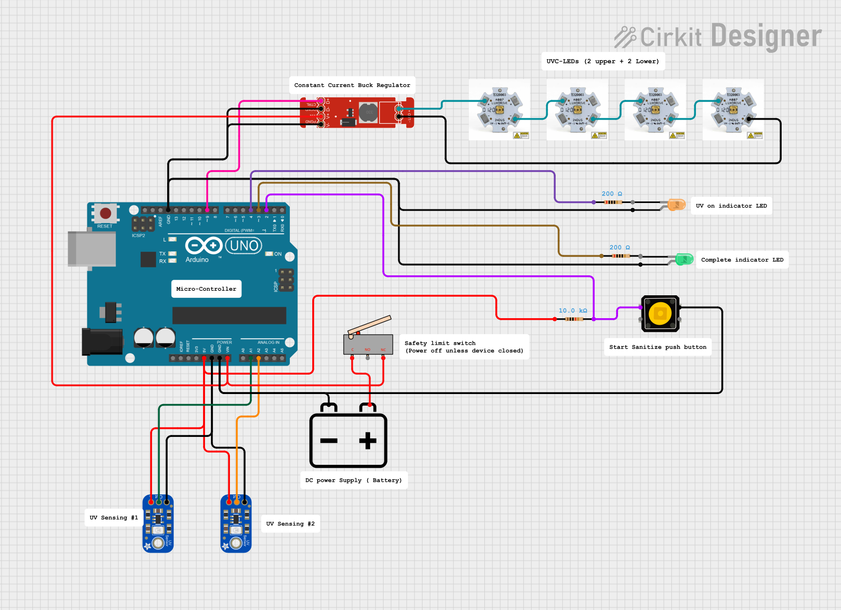
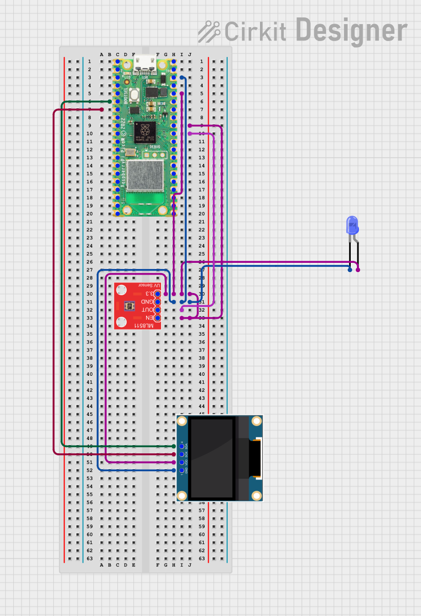
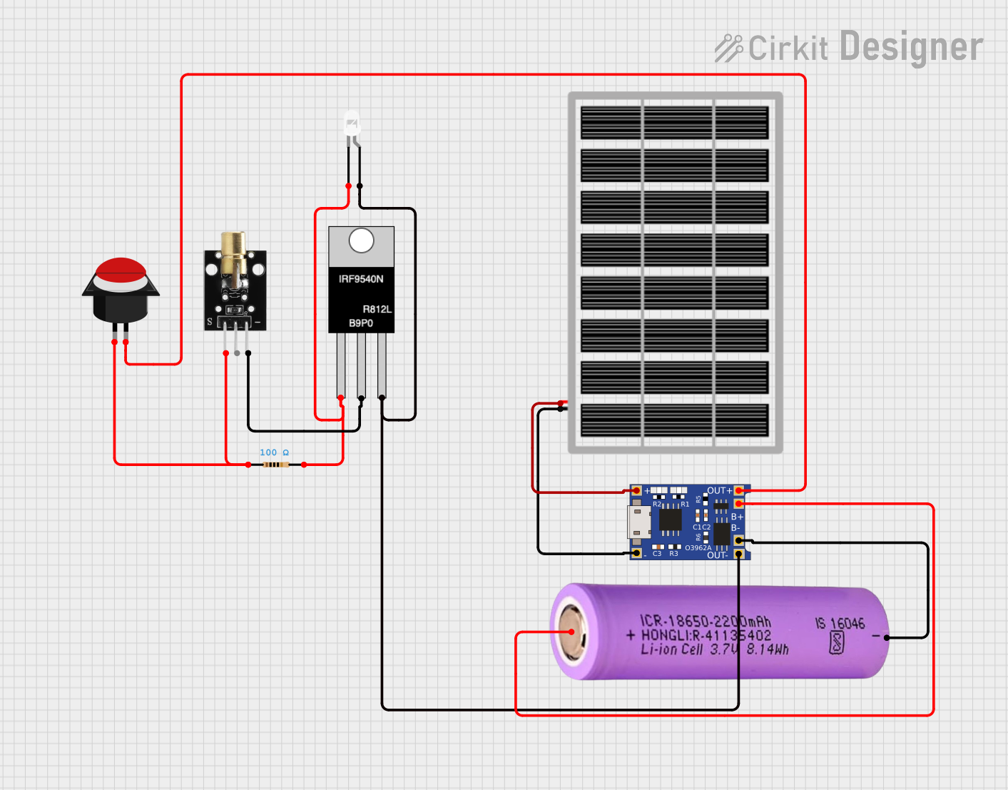

Explore Projects Built with High Power 265-nm COB UV-C LED
Common Applications and Use Cases
- Water purification: Effective in sterilizing water by eliminating harmful microorganisms.
- Air disinfection: Used in HVAC systems to purify air in residential, commercial, and industrial spaces.
- Surface sterilization: Ideal for medical equipment, laboratory tools, and high-touch surfaces.
- Food and beverage processing: Ensures hygiene by reducing microbial contamination.
- Healthcare environments: Used in hospitals and clinics for sterilizing rooms and equipment.
Technical Specifications
Key Technical Details
| Parameter | Value |
|---|---|
| Wavelength | 265 nm |
| Optical Power Output | 48 mW |
| Forward Voltage (Vf) | 6.0 V (typical) |
| Forward Current (If) | 500 mA (typical) |
| Power Consumption | 3 W |
| Viewing Angle | 120° |
| Thermal Resistance (Rth) | 2.5 °C/W |
| Operating Temperature | -30°C to +85°C |
| Storage Temperature | -40°C to +100°C |
| Package Type | COB (Chip-on-Board) |
| Lifespan | >10,000 hours (at rated conditions) |
Pin Configuration and Descriptions
The VC2X2C48L6-265-V1 COB UV-C LED has two solder pads for electrical connections. Below is the pin configuration:
| Pin Number | Pin Name | Description |
|---|---|---|
| 1 | Anode | Positive terminal for power input. |
| 2 | Cathode | Negative terminal for power input. |
Usage Instructions
How to Use the Component in a Circuit
- Power Supply: Use a constant current LED driver capable of supplying 500 mA at 6.0 V. Ensure the driver has overcurrent and overvoltage protection to prevent damage to the LED.
- Thermal Management: Mount the COB LED on a heat sink with thermal paste to dissipate heat effectively. This is critical to maintain performance and extend the lifespan of the LED.
- Circuit Design:
- Connect the Anode to the positive output of the LED driver.
- Connect the Cathode to the negative output of the LED driver.
- Safety Precautions:
- Avoid direct exposure to UV-C light, as it can harm skin and eyes.
- Use protective eyewear and clothing when working with the LED.
- Enclose the LED in a UV-safe housing to prevent accidental exposure.
Important Considerations and Best Practices
- Current Regulation: Always use a constant current driver to prevent overdriving the LED, which can reduce its lifespan.
- Thermal Monitoring: Ensure the heat sink is adequate for the operating conditions. Use a thermal sensor if necessary to monitor the temperature.
- Environmental Conditions: Avoid operating the LED in environments with high humidity or corrosive gases, as these can degrade the performance of the LED.
- Wiring: Use short, low-resistance wires to minimize voltage drops and ensure stable operation.
Example: Connecting to an Arduino UNO
While the VC2X2C48L6-265-V1 is not directly compatible with an Arduino UNO due to its high power requirements, you can use the Arduino to control the LED via a relay or MOSFET. Below is an example circuit and code for controlling the LED with a MOSFET:
Circuit Diagram
- Connect the Anode of the LED to the positive terminal of the power supply.
- Connect the Cathode of the LED to the Drain of an N-channel MOSFET (e.g., IRF540N).
- Connect the Source of the MOSFET to the ground of the power supply.
- Connect the Gate of the MOSFET to a PWM-capable pin on the Arduino (e.g., Pin 9) through a 220-ohm resistor.
- Add a 10k-ohm pull-down resistor between the Gate and Source of the MOSFET.
Arduino Code
// UV-C LED Control with Arduino UNO
// This code uses PWM to control the brightness of the UV-C LED.
// Ensure the LED is connected via a MOSFET and a constant current driver.

const int ledPin = 9; // PWM pin connected to the MOSFET Gate

void setup() {
  pinMode(ledPin, OUTPUT); // Set the LED pin as an output
}

void loop() {
  // Gradually increase brightness
  for (int brightness = 0; brightness <= 255; brightness++) {
    analogWrite(ledPin, brightness); // Set PWM duty cycle
    delay(10); // Wait 10 ms
  }

  // Gradually decrease brightness
  for (int brightness = 255; brightness >= 0; brightness--) {
    analogWrite(ledPin, brightness); // Set PWM duty cycle
    delay(10); // Wait 10 ms
  }
}
Troubleshooting and FAQs
Common Issues and Solutions
| Issue | Possible Cause | Solution |
|---|---|---|
| LED does not light up | Incorrect wiring or insufficient power | Verify connections and power supply. |
| LED flickers | Unstable power supply or loose wiring | Use a stable constant current driver and check connections. |
| LED overheats | Inadequate heat dissipation | Use a larger heat sink or improve thermal paste application. |
| Reduced UV output over time | Overdriving the LED or poor cooling | Ensure proper current regulation and thermal management. |
FAQs
- Can I power the LED directly from a battery?
- No, the LED requires a constant current driver to operate safely and efficiently.
- What safety precautions should I take when using this LED?
- Avoid direct exposure to UV-C light, as it can harm skin and eyes. Always use protective gear and enclosures.
- Can I dim the LED?
- Yes, you can dim the LED using a PWM signal to control the constant current driver or a MOSFET circuit.
- What is the expected lifespan of the LED?
- The LED has a lifespan of over 10,000 hours when operated under rated conditions.
This concludes the documentation for the High Power 265-nm COB UV-C LED (VC2X2C48L6-265-V1) by Violumas.