Cirkit Designer
Your all-in-one circuit design IDE
Home /
Component Documentation
How to Use Servo: Examples, Pinouts, and Specs
Introduction
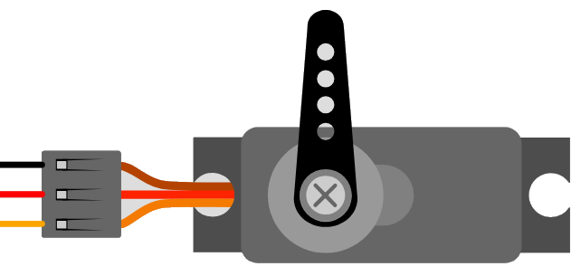
A servo motor is a rotary or linear actuator that allows for precise control of angular or linear position, velocity, and acceleration. It consists of a suitable motor coupled to a sensor for position feedback. Servo motors are widely used in various applications due to their precision and reliability.
Explore Projects Built with Servo
Arduino Mega 2560 Controlled Multi-Servo Random Positioning System

This circuit consists of an Arduino Mega 2560 microcontroller connected to twelve servo motors, each individually controlled by a distinct PWM pin on the Arduino. The servos are powered by a single Polymer Lithium Ion Battery, with all servos sharing a common power (VCC) and ground (GND) connection. The embedded code on the Arduino is designed to randomly position each servo within a 0 to 180-degree range, with a random delay between movements, demonstrating a multi-servo control system possibly for applications like robotics or animatronics.
Arduino UNO Servo Motor Controller
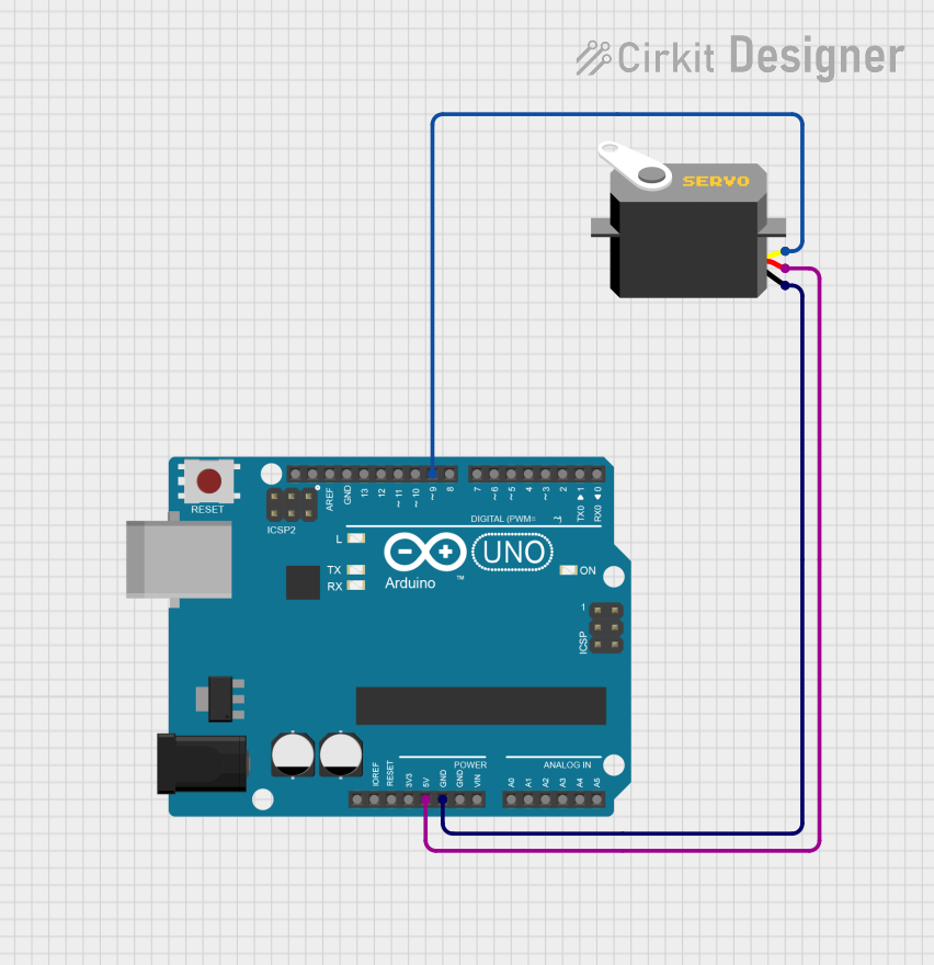
This circuit consists of an Arduino UNO microcontroller connected to a servo motor. The Arduino provides power (5V and GND) to the servo and controls its position through a pulse signal on pin D9. The embedded code on the Arduino is programmed to smoothly move the servo between 0 and 180 degrees, creating a sweeping motion.
Arduino UNO Controlled Servo Motor
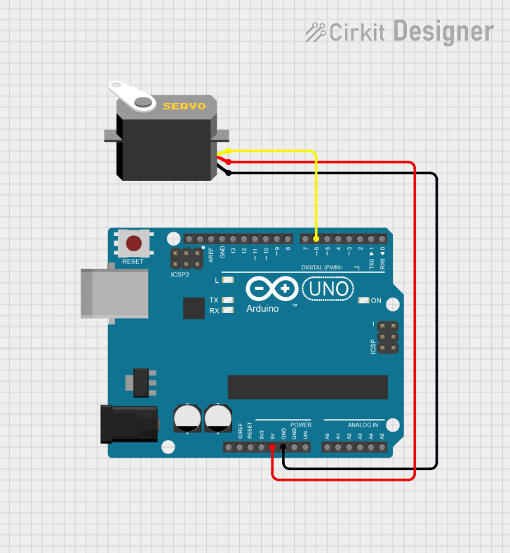
This circuit consists of an Arduino UNO microcontroller connected to a servo motor. The Arduino provides power (5V) and ground connections to the servo, as well as a control signal through one of its digital pins (D6). The embedded code on the Arduino is set up to control the servo's position, sending it to a fixed angle upon each loop iteration.
Arduino-Controlled Multi-Servo System
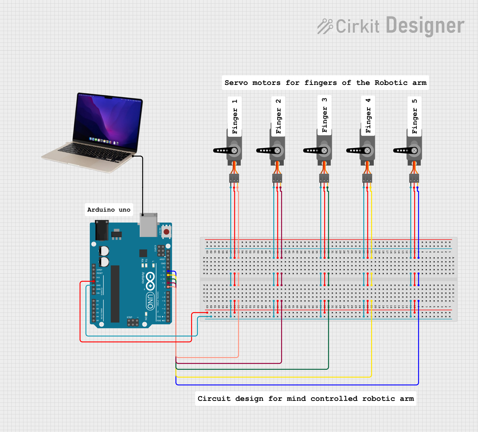
This circuit consists of an Arduino UNO microcontroller connected to five servo motors. The servos are powered by the Arduino's 5V output and share a common ground. Each servo's PWM control pin is individually connected to a digital pin on the Arduino (D8, D9, D10, D11, D12), allowing for independent control of each servo's position. The Arduino is also connected to a laptop via USB for programming and power.
Explore Projects Built with Servo
Arduino Mega 2560 Controlled Multi-Servo Random Positioning System
This circuit consists of an Arduino Mega 2560 microcontroller connected to twelve servo motors, each individually controlled by a distinct PWM pin on the Arduino. The servos are powered by a single Polymer Lithium Ion Battery, with all servos sharing a common power (VCC) and ground (GND) connection. The embedded code on the Arduino is designed to randomly position each servo within a 0 to 180-degree range, with a random delay between movements, demonstrating a multi-servo control system possibly for applications like robotics or animatronics.
Arduino UNO Servo Motor Controller
This circuit consists of an Arduino UNO microcontroller connected to a servo motor. The Arduino provides power (5V and GND) to the servo and controls its position through a pulse signal on pin D9. The embedded code on the Arduino is programmed to smoothly move the servo between 0 and 180 degrees, creating a sweeping motion.
Arduino UNO Controlled Servo Motor
This circuit consists of an Arduino UNO microcontroller connected to a servo motor. The Arduino provides power (5V) and ground connections to the servo, as well as a control signal through one of its digital pins (D6). The embedded code on the Arduino is set up to control the servo's position, sending it to a fixed angle upon each loop iteration.
Arduino-Controlled Multi-Servo System
This circuit consists of an Arduino UNO microcontroller connected to five servo motors. The servos are powered by the Arduino's 5V output and share a common ground. Each servo's PWM control pin is individually connected to a digital pin on the Arduino (D8, D9, D10, D11, D12), allowing for independent control of each servo's position. The Arduino is also connected to a laptop via USB for programming and power.
Common Applications and Use Cases
- Robotics: For precise movement and control of robotic arms and joints.
- RC Vehicles: Used in remote-controlled cars, boats, and airplanes for steering and throttle control.
- Industrial Automation: For controlling conveyor belts, robotic assembly lines, and other automated machinery.
- Aerospace: In aircraft control systems for adjusting flaps, rudders, and other control surfaces.
- Home Automation: In smart home devices like automated blinds, locks, and cameras.
Technical Specifications
Key Technical Details
| Parameter | Value |
|---|---|
| Operating Voltage | 4.8V to 6.0V |
| Operating Current | 100mA to 1A (depending on load) |
| Stall Torque | 1.5 kg-cm to 20 kg-cm |
| Speed | 0.1s/60° to 0.2s/60° |
| Control Signal | PWM (Pulse Width Modulation) |
| Angle Range | 0° to 180° (standard) |
| Connector Type | 3-pin (GND, VCC, Signal) |
Pin Configuration and Descriptions
| Pin Number | Pin Name | Description |
|---|---|---|
| 1 | GND | Ground connection |
| 2 | VCC | Power supply (4.8V to 6.0V) |
| 3 | Signal | PWM control signal for position |
Usage Instructions
How to Use the Servo Motor in a Circuit
- Power Supply: Connect the VCC pin to a 5V power supply and the GND pin to the ground of the power supply.
- Control Signal: Connect the Signal pin to a PWM-capable pin on your microcontroller (e.g., Arduino UNO).
- PWM Signal: Generate a PWM signal to control the position of the servo. The pulse width typically ranges from 1ms to 2ms, corresponding to 0° to 180°.
Important Considerations and Best Practices
- Power Supply: Ensure that the power supply can provide sufficient current, especially if multiple servos are used.
- Heat Dissipation: Avoid continuous stalling of the servo to prevent overheating.
- Signal Integrity: Use short and shielded cables for the signal line to avoid noise interference.
- Calibration: Calibrate the servo to ensure accurate positioning.
Example Code for Arduino UNO
#include <Servo.h> // Include the Servo library

Servo myServo; // Create a Servo object

void setup() {
  myServo.attach(9); // Attach the servo to pin 9
}

void loop() {
  myServo.write(0); // Move servo to 0 degrees
  delay(1000); // Wait for 1 second
  myServo.write(90); // Move servo to 90 degrees
  delay(1000); // Wait for 1 second
  myServo.write(180); // Move servo to 180 degrees
  delay(1000); // Wait for 1 second
}
Troubleshooting and FAQs
Common Issues Users Might Face
Servo Not Moving:
- Solution: Check the power supply and ensure it is within the specified voltage range. Verify the connections and ensure the signal pin is correctly connected to a PWM-capable pin.
Servo Jittering:
- Solution: Ensure a stable power supply. Use capacitors to filter noise and stabilize the voltage. Check for loose connections.
Overheating:
- Solution: Avoid continuous stalling and ensure the servo is not overloaded. Provide adequate ventilation.
FAQs
Q1: Can I use a servo motor with a 3.3V microcontroller?
- A1: Yes, but you need a level shifter to convert the 3.3V signal to 5V for the servo's control signal.
Q2: How do I increase the torque of my servo motor?
- A2: Use a servo with a higher torque rating or use a mechanical advantage like gears or levers.
Q3: Can I control multiple servos with one Arduino?
- A3: Yes, you can control multiple servos using different PWM pins. The Servo library supports up to 12 servos on most Arduino boards.
By following this documentation, users can effectively utilize servo motors in their projects, ensuring precise control and reliable performance.