How to Use RP LiDAR C1: Examples, Pinouts, and Specs
Introduction
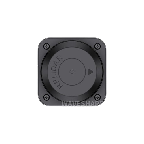
The RP LiDAR C1, manufactured by SLAMTEC, is a compact and high-performance LiDAR sensor designed for precise distance measurement and 3D mapping. Utilizing advanced laser technology, the RP LiDAR C1 scans its surroundings to provide real-time data, making it an essential component for applications in robotics, autonomous vehicles, geographic information systems (GIS), and more.
Explore Projects Built with RP LiDAR C1
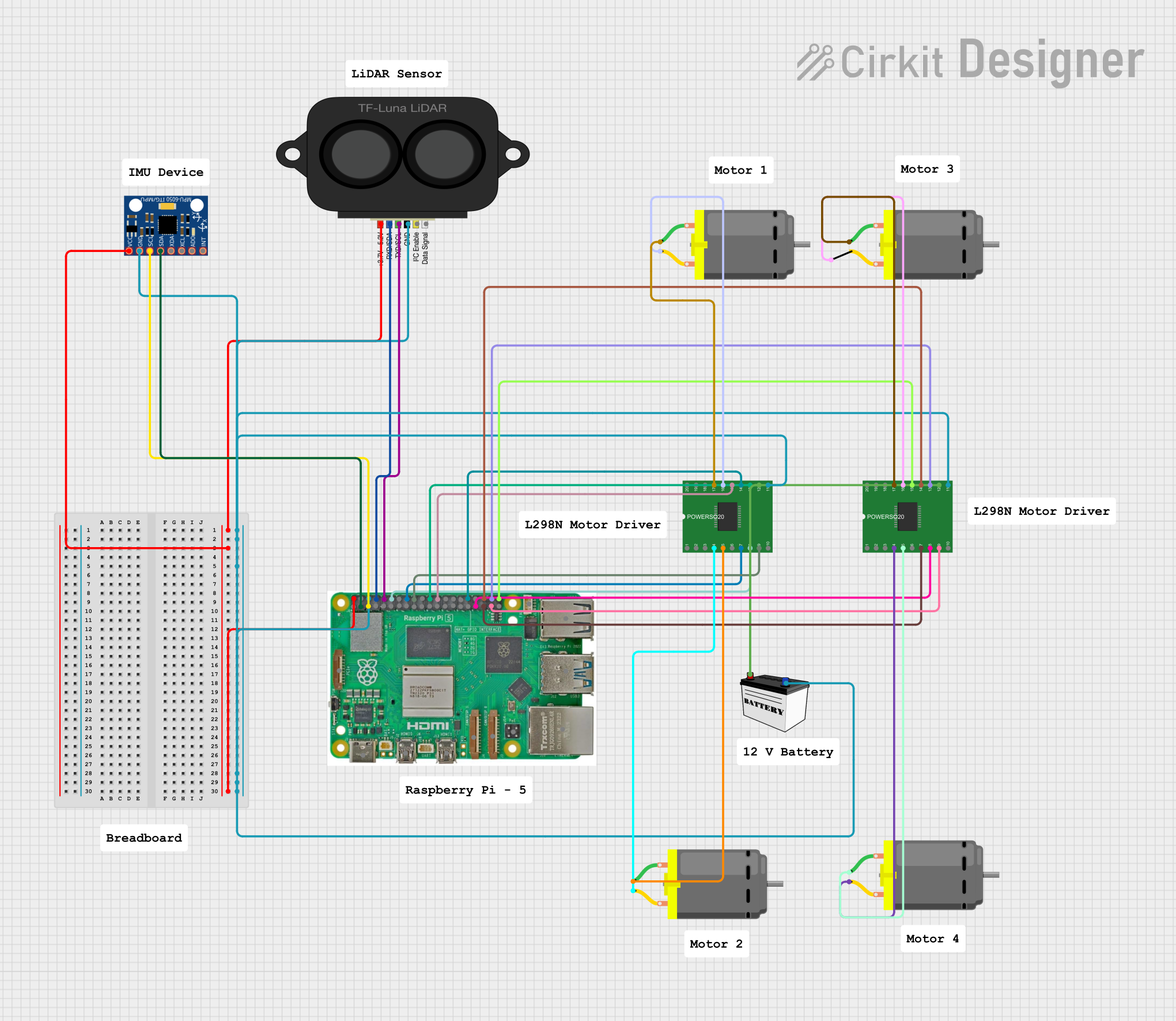
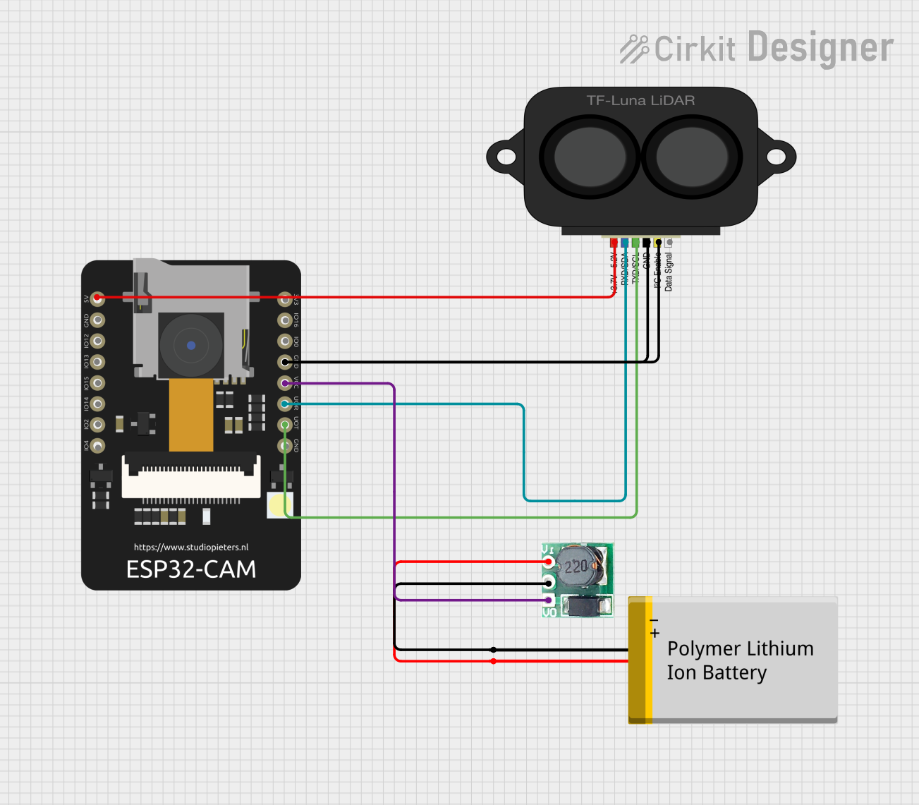
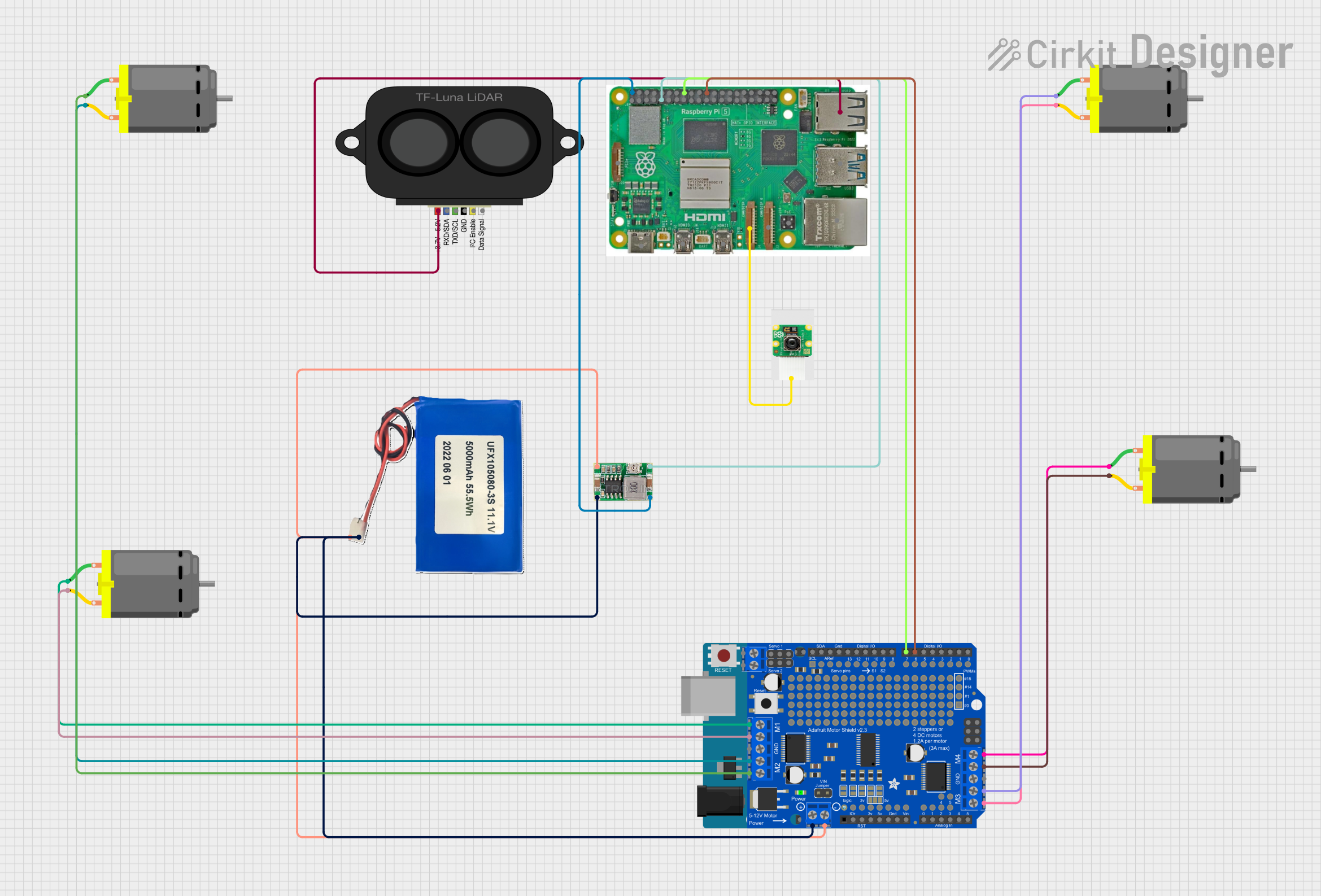

Explore Projects Built with RP LiDAR C1
Common Applications
- Robotics: Navigation, obstacle detection, and mapping for autonomous robots.
- Autonomous Vehicles: Real-time environment scanning for collision avoidance and path planning.
- Geographic Information Systems (GIS): 3D mapping and terrain analysis.
- Industrial Automation: Object detection and spatial awareness in automated systems.
Technical Specifications
The RP LiDAR C1 is designed to deliver reliable performance in a compact form factor. Below are its key technical details:
General Specifications
| Parameter | Value |
|---|---|
| Measurement Range | 0.15 m to 12 m |
| Scanning Frequency | 6 Hz to 12 Hz (adjustable) |
| Angular Resolution | 1° to 2° |
| Distance Resolution | < 1% of the measured distance |
| Laser Wavelength | 785 nm (infrared) |
| Laser Safety Class | Class 1 (eye-safe) |
| Communication Interface | UART (3.3V TTL) |
| Operating Voltage | 5 V DC |
| Power Consumption | < 2.5 W |
| Dimensions | 70 mm × 70 mm × 41 mm |
| Weight | 190 g |
Pin Configuration
The RP LiDAR C1 features a 5-pin interface for power and communication. Below is the pinout description:
| Pin Number | Name | Description |
|---|---|---|
| 1 | VCC | Power input (5 V DC) |
| 2 | GND | Ground |
| 3 | TX | UART Transmit (3.3V TTL) |
| 4 | RX | UART Receive (3.3V TTL) |
| 5 | Motor Enable | Motor control signal (active high) |
Usage Instructions
Connecting the RP LiDAR C1
- Power Supply: Connect the VCC pin to a 5V DC power source and the GND pin to ground.
- Communication: Use the TX and RX pins to establish a UART connection with a microcontroller or computer. Ensure the UART voltage level is 3.3V TTL.
- Motor Control: Use the Motor Enable pin to start or stop the LiDAR's motor. Set the pin high to enable the motor and low to disable it.
Using with Arduino UNO
To interface the RP LiDAR C1 with an Arduino UNO, you will need a logic level shifter to convert the 3.3V UART signals to 5V. Below is an example code snippet to read data from the LiDAR:
#include <SoftwareSerial.h>

// Define RX and TX pins for SoftwareSerial
SoftwareSerial lidarSerial(10, 11); // RX = Pin 10, TX = Pin 11

void setup() {
  Serial.begin(9600); // Initialize Serial Monitor
  lidarSerial.begin(115200); // Initialize LiDAR UART communication

  pinMode(9, OUTPUT); // Motor Enable pin
  digitalWrite(9, HIGH); // Enable LiDAR motor
  delay(1000); // Wait for the motor to stabilize
}

void loop() {
  if (lidarSerial.available()) {
    // Read and print data from the LiDAR
    char data = lidarSerial.read();
    Serial.print(data);
  }
}
Best Practices
- Power Supply: Use a stable 5V DC power source to avoid performance issues.
- UART Communication: Ensure proper voltage level matching between the LiDAR and the microcontroller.
- Environment: Avoid exposing the LiDAR to direct sunlight or reflective surfaces, as these can interfere with measurements.
Troubleshooting and FAQs
Common Issues and Solutions
No Data Output:
- Cause: Incorrect UART connection or baud rate mismatch.
- Solution: Verify the TX and RX connections and ensure the baud rate is set to 115200.
Inaccurate Measurements:
- Cause: Reflective or transparent surfaces in the scanning area.
- Solution: Avoid scanning highly reflective or transparent objects.
Motor Not Spinning:
- Cause: Motor Enable pin not set high.
- Solution: Check the Motor Enable pin connection and ensure it is set to HIGH.
Overheating:
- Cause: Prolonged operation in high-temperature environments.
- Solution: Ensure adequate ventilation and avoid operating the LiDAR in temperatures above 40°C.
FAQs
Q: Can the RP LiDAR C1 be used outdoors?
- A: Yes, but avoid direct sunlight and extreme weather conditions for optimal performance.
Q: What is the maximum range of the RP LiDAR C1?
- A: The maximum range is 12 meters under standard operating conditions.
Q: Is the laser safe for human eyes?
- A: Yes, the RP LiDAR C1 uses a Class 1 laser, which is eye-safe.
Q: Can I adjust the scanning frequency?
- A: Yes, the scanning frequency can be adjusted between 6 Hz and 12 Hz via software commands.
This documentation provides a comprehensive guide to using the RP LiDAR C1 effectively. For further assistance, refer to the official SLAMTEC user manual.