Cirkit Designer
Your all-in-one circuit design IDE
Home /
Component Documentation
How to Use CD4052BE: Examples, Pinouts, and Specs
Introduction
The CD4052BE, manufactured by Texas Instruments, is a dual 4-channel analog multiplexer/demultiplexer. This versatile component is designed to route analog or digital signals to a common output or input, making it an essential part of many electronic circuits. With its low ON resistance and low OFF leakage current, the CD4052BE ensures minimal signal loss and high fidelity in signal routing applications.
Explore Projects Built with CD4052BE
Arduino UNO with MPU-6050 Sensor Array and Multiplexer Control Circuit
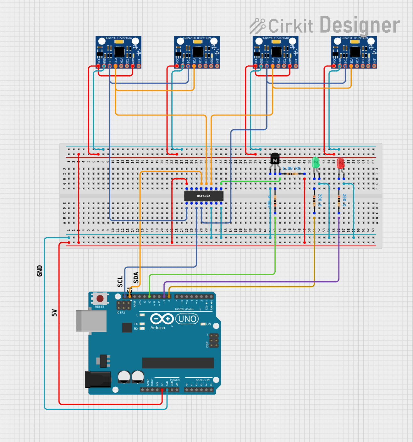
This circuit is designed to interface multiple MPU-6050 sensors with an Arduino UNO for motion tracking purposes. The HCF4052BE analog multiplexer/demultiplexer is used to switch between the MPU-6050 sensors' SCL and SDA lines, allowing for multiple sensors to share the same I2C bus. The Arduino runs embedded code to read capacitive touch inputs, accelerometer and gyroscope data from the MPU-6050 sensors, and transmit this information via Bluetooth and Wi-Fi using software serial communication.
Bluetooth-Controlled Multi-Function Arduino Nano Gadget

This is a portable, microcontroller-driven interactive device featuring Bluetooth connectivity, visual (RGB LED), auditory (loudspeaker), and haptic (vibration motor) feedback, user input (pushbutton), and a rechargeable power system (TP4056 with Li-ion battery).
ESP32-Powered Wi-Fi Controlled Robotic Car with OLED Display and Ultrasonic Sensor

This circuit is a battery-powered system featuring an ESP32 microcontroller that controls an OLED display, a motor driver for two hobby motors, an ultrasonic sensor for distance measurement, and a DFPlayer Mini for audio output through a loudspeaker. The TP4056 module manages battery charging, and a step-up boost converter provides a stable 5V supply to the components.
Arduino Nano 33 BLE Battery-Powered Display Interface

This circuit features a Nano 33 BLE microcontroller interfaced with a TM1637 4-digit 7-segment display for information output, powered by a 3.7V battery managed by a TP4056 charging module. The microcontroller communicates with the display to present data, while the TP4056 ensures the battery is charged safely and provides power to the system.
Explore Projects Built with CD4052BE
Arduino UNO with MPU-6050 Sensor Array and Multiplexer Control Circuit
This circuit is designed to interface multiple MPU-6050 sensors with an Arduino UNO for motion tracking purposes. The HCF4052BE analog multiplexer/demultiplexer is used to switch between the MPU-6050 sensors' SCL and SDA lines, allowing for multiple sensors to share the same I2C bus. The Arduino runs embedded code to read capacitive touch inputs, accelerometer and gyroscope data from the MPU-6050 sensors, and transmit this information via Bluetooth and Wi-Fi using software serial communication.
Bluetooth-Controlled Multi-Function Arduino Nano Gadget
This is a portable, microcontroller-driven interactive device featuring Bluetooth connectivity, visual (RGB LED), auditory (loudspeaker), and haptic (vibration motor) feedback, user input (pushbutton), and a rechargeable power system (TP4056 with Li-ion battery).
ESP32-Powered Wi-Fi Controlled Robotic Car with OLED Display and Ultrasonic Sensor
This circuit is a battery-powered system featuring an ESP32 microcontroller that controls an OLED display, a motor driver for two hobby motors, an ultrasonic sensor for distance measurement, and a DFPlayer Mini for audio output through a loudspeaker. The TP4056 module manages battery charging, and a step-up boost converter provides a stable 5V supply to the components.
Arduino Nano 33 BLE Battery-Powered Display Interface
This circuit features a Nano 33 BLE microcontroller interfaced with a TM1637 4-digit 7-segment display for information output, powered by a 3.7V battery managed by a TP4056 charging module. The microcontroller communicates with the display to present data, while the TP4056 ensures the battery is charged safely and provides power to the system.
Common Applications and Use Cases
- Signal Routing: Used to switch between multiple analog or digital signals.
- Data Acquisition Systems: Helps in selecting different sensors or input sources.
- Audio Systems: Routes audio signals to different channels.
- Communication Systems: Manages multiple data lines.
- Instrumentation: Used in measurement systems to select different input signals.
Technical Specifications
Key Technical Details
| Parameter | Value |
|---|---|
| Supply Voltage (VDD) | 3V to 15V |
| Input Voltage Range | 0V to VDD |
| ON Resistance (RON) | 125Ω (typical) at VDD = 10V |
| OFF Leakage Current | ±100pA (typical) at VDD = 10V |
| Operating Temperature | -55°C to 125°C |
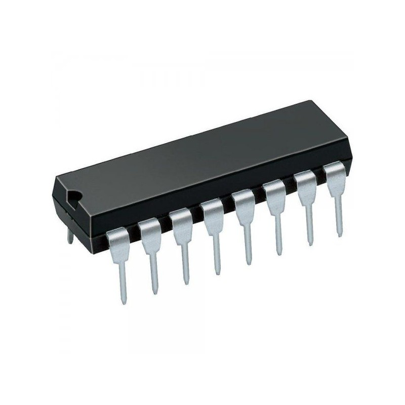
| Package | PDIP-16 |
Pin Configuration and Descriptions
| Pin No. | Pin Name | Description |
|---|---|---|
| 1 | X0 | Channel 0 of multiplexer X |
| 2 | X1 | Channel 1 of multiplexer X |
| 3 | X2 | Channel 2 of multiplexer X |
| 4 | X3 | Channel 3 of multiplexer X |
| 5 | IN/OUT X | Common input/output for multiplexer X |
| 6 | IN/OUT Y | Common input/output for multiplexer Y |
| 7 | Y3 | Channel 3 of multiplexer Y |
| 8 | Y2 | Channel 2 of multiplexer Y |
| 9 | Y1 | Channel 1 of multiplexer Y |
| 10 | Y0 | Channel 0 of multiplexer Y |
| 11 | VSS | Ground |
| 12 | A | Address select bit A |
| 13 | B | Address select bit B |
| 14 | INH | Inhibit (active high) |
| 15 | VDD | Positive supply voltage |
| 16 | COM | Common terminal for both multiplexers |
Usage Instructions
How to Use the Component in a Circuit
- Power Supply: Connect VDD to the positive supply voltage (3V to 15V) and VSS to ground.
- Signal Connections: Connect the signals you want to route to the X0-X3 and Y0-Y3 pins.
- Common I/O: Connect the common input/output signals to the IN/OUT X and IN/OUT Y pins.
- Address Selection: Use the A and B pins to select the desired channel. The combination of A and B determines which channel is connected to the common I/O.
- Inhibit Control: Use the INH pin to disable the multiplexer. When INH is high, all channels are disconnected.
Important Considerations and Best Practices
- Decoupling Capacitors: Place decoupling capacitors (0.1µF) close to the VDD pin to filter out noise.
- Signal Integrity: Keep signal traces as short as possible to minimize noise and signal degradation.
- Unused Channels: If any channels are not used, connect them to ground to avoid floating inputs.
- Inhibit Pin: Use the INH pin to disable the multiplexer when not in use to save power and reduce noise.
Example Circuit with Arduino UNO
/*
 * Example code to demonstrate the use of CD4052BE with Arduino UNO.
 * This code selects different channels of the multiplexer and reads
 * analog signals from them.
 */

const int A_PIN = 2; // Address pin A connected to digital pin 2
const int B_PIN = 3; // Address pin B connected to digital pin 3
const int INH_PIN = 4; // Inhibit pin connected to digital pin 4
const int IN_OUT_X_PIN = A0; // Common I/O pin connected to analog pin A0

void setup() {
  pinMode(A_PIN, OUTPUT);
  pinMode(B_PIN, OUTPUT);
  pinMode(INH_PIN, OUTPUT);
  digitalWrite(INH_PIN, LOW); // Enable the multiplexer
  Serial.begin(9600);
}

void loop() {
  for (int channel = 0; channel < 4; channel++) {
    selectChannel(channel);
    int sensorValue = analogRead(IN_OUT_X_PIN);
    Serial.print("Channel ");
    Serial.print(channel);
    Serial.print(": ");
    Serial.println(sensorValue);
    delay(1000);
  }
}

void selectChannel(int channel) {
  digitalWrite(A_PIN, channel & 0x01);
  digitalWrite(B_PIN, (channel >> 1) & 0x01);
}
Troubleshooting and FAQs
Common Issues Users Might Face
No Signal Output:
- Solution: Check the power supply connections (VDD and VSS). Ensure the INH pin is low to enable the multiplexer.
High Signal Loss:
- Solution: Verify that the signal levels are within the specified input voltage range. Check for proper grounding and minimize trace lengths.
Unexpected Channel Selection:
- Solution: Ensure the address pins (A and B) are correctly set. Check for loose connections or shorts.
Solutions and Tips for Troubleshooting
- Check Connections: Ensure all connections are secure and correctly wired according to the pin configuration.
- Verify Power Supply: Make sure the supply voltage is within the specified range (3V to 15V).
- Use Decoupling Capacitors: Place capacitors close to the VDD pin to filter out noise.
- Test Individual Channels: Test each channel individually to isolate any issues.
By following this documentation, users can effectively integrate the CD4052BE into their electronic projects, ensuring reliable and efficient signal routing.