How to Use ESP32-2432S028: Examples, Pinouts, and Specs
Introduction
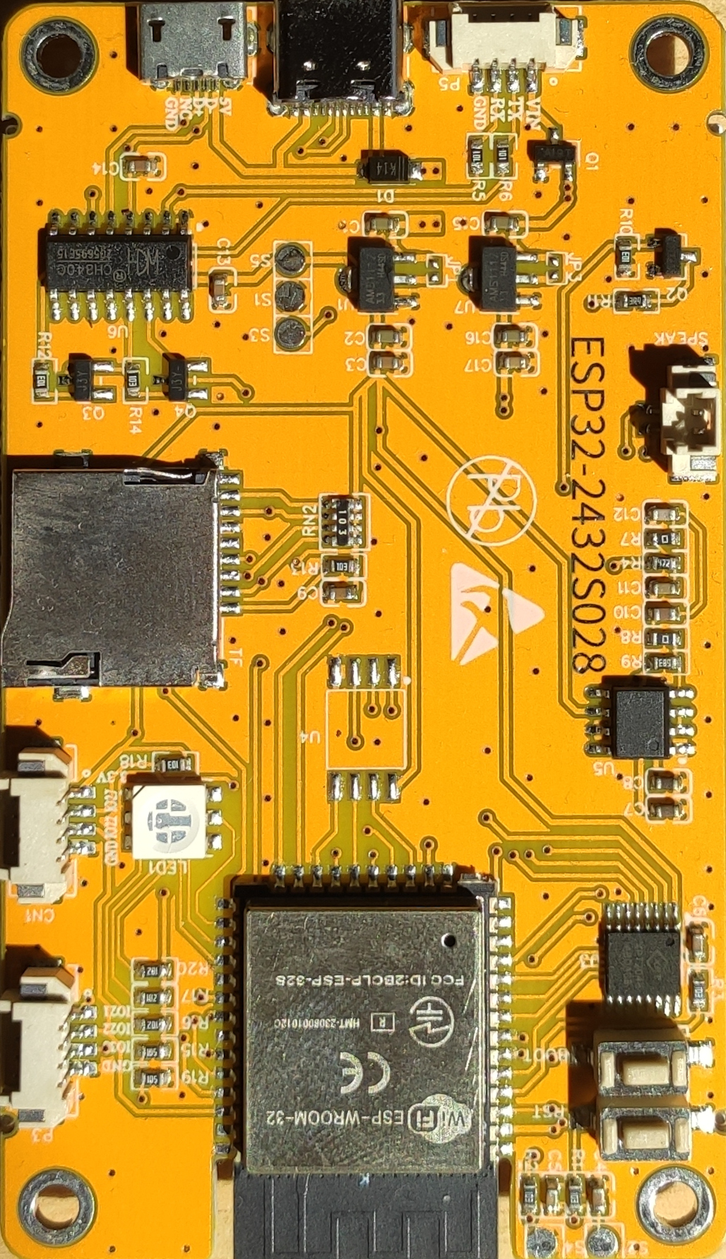
The ESP32-2432S028 is a powerful microcontroller module that integrates Wi-Fi and Bluetooth capabilities, making it an ideal choice for Internet of Things (IoT) applications and embedded systems. It features a dual-core processor, enabling efficient multitasking and high-performance computing. This module is widely used in smart home devices, industrial automation, wearable electronics, and other wireless communication projects.
Explore Projects Built with ESP32-2432S028


Explore Projects Built with ESP32-2432S028
Common Applications and Use Cases
- IoT devices and smart home automation
- Wireless sensor networks
- Wearable technology
- Industrial control systems
- Robotics and drones
- Real-time data monitoring and logging
Technical Specifications
The ESP32-2432S028 is designed to deliver robust performance while maintaining low power consumption. Below are its key technical details:
Key Technical Details
| Parameter | Specification |
|---|---|
| Processor | Dual-core Xtensa® 32-bit LX6 CPU |
| Clock Speed | Up to 240 MHz |
| Flash Memory | 4 MB |
| SRAM | 520 KB |
| Wireless Connectivity | Wi-Fi 802.11 b/g/n, Bluetooth v4.2 |
| Operating Voltage | 3.3V |
| GPIO Pins | 28 |
| Communication Interfaces | UART, SPI, I2C, I2S, PWM, ADC, DAC |
| ADC Resolution | 12-bit |
| Operating Temperature | -40°C to +85°C |
| Dimensions | 28 mm x 32 mm |
Pin Configuration and Descriptions
The ESP32-2432S028 module features a 28-pin layout. Below is the pin configuration:
| Pin Number | Pin Name | Function |
|---|---|---|
| 1 | GND | Ground |
| 2 | 3V3 | 3.3V Power Supply |
| 3 | EN | Enable Pin (Active High) |
| 4 | IO0 | GPIO0, Boot Mode Selection |
| 5 | IO1 | GPIO1, UART TX |
| 6 | IO2 | GPIO2, General Purpose I/O |
| 7 | IO3 | GPIO3, UART RX |
| 8 | IO4 | GPIO4, PWM Output |
| 9 | IO5 | GPIO5, SPI Clock (SCK) |
| 10 | IO12 | GPIO12, ADC Input |
| 11 | IO13 | GPIO13, SPI MOSI |
| 12 | IO14 | GPIO14, SPI MISO |
| 13 | IO15 | GPIO15, PWM Output |
| 14 | IO16 | GPIO16, I2C SDA |
| 15 | IO17 | GPIO17, I2C SCL |
| 16 | IO18 | GPIO18, SPI Clock |
| 17 | IO19 | GPIO19, General Purpose I/O |
| 18 | IO21 | GPIO21, I2C SDA |
| 19 | IO22 | GPIO22, I2C SCL |
| 20 | IO23 | GPIO23, SPI MOSI |
| 21 | IO25 | GPIO25, DAC Output |
| 22 | IO26 | GPIO26, DAC Output |
| 23 | IO27 | GPIO27, ADC Input |
| 24 | IO32 | GPIO32, ADC Input |
| 25 | IO33 | GPIO33, ADC Input |
| 26 | IO34 | GPIO34, ADC Input |
| 27 | IO35 | GPIO35, ADC Input |
| 28 | IO39 | GPIO39, ADC Input |
Usage Instructions
The ESP32-2432S028 is versatile and easy to use in a variety of applications. Below are the steps and best practices for using this module in a circuit.
How to Use the Component in a Circuit
- Power Supply: Connect the 3V3 pin to a 3.3V power source and the GND pin to ground.
- Programming: Use a USB-to-serial adapter to program the ESP32. Connect the adapter's TX pin to GPIO3 (RX) and RX pin to GPIO1 (TX).
- Boot Mode: To upload code, hold GPIO0 low while resetting the module.
- Peripherals: Connect sensors, actuators, or other peripherals to the GPIO pins as needed. Use appropriate pull-up or pull-down resistors for stable operation.
- Communication: Use UART, SPI, or I2C interfaces to communicate with other devices.
Important Considerations and Best Practices
- Ensure the power supply is stable and within the 3.3V range to avoid damaging the module.
- Use level shifters if interfacing with 5V logic devices.
- Avoid leaving unused GPIO pins floating; tie them to ground or VCC through resistors.
- Use decoupling capacitors near the power pins to reduce noise.
- For wireless applications, ensure the antenna area is free from obstructions for optimal signal strength.
Example Code for Arduino UNO
The ESP32-2432S028 can be programmed using the Arduino IDE. Below is an example of how to connect the module to Wi-Fi and print the IP address:
#include <WiFi.h> // Include the WiFi library for ESP32

const char* ssid = "Your_SSID";       // Replace with your Wi-Fi SSID
const char* password = "Your_Password"; // Replace with your Wi-Fi password

void setup() {
  Serial.begin(115200); // Initialize serial communication at 115200 baud
  delay(1000);          // Wait for a second to stabilize

  Serial.println("Connecting to Wi-Fi...");
  WiFi.begin(ssid, password); // Start Wi-Fi connection

  while (WiFi.status() != WL_CONNECTED) {
    delay(500); // Wait for connection
    Serial.print(".");
  }

  Serial.println("\nWi-Fi connected!");
  Serial.print("IP Address: ");
  Serial.println(WiFi.localIP()); // Print the assigned IP address
}

void loop() {
  // Add your main code here
}
Troubleshooting and FAQs
Common Issues Users Might Face
Module Not Responding:
- Ensure the power supply is stable and within the 3.3V range.
- Check the connections, especially the TX and RX pins.
Wi-Fi Connection Fails:
- Verify the SSID and password are correct.
- Ensure the router is within range and not overloaded with devices.
Code Upload Fails:
- Ensure GPIO0 is held low during the reset for boot mode.
- Check the USB-to-serial adapter connections.
Unstable Operation:
- Add decoupling capacitors near the power pins.
- Avoid using long wires for high-frequency signals.
Solutions and Tips for Troubleshooting
- Use a multimeter to check voltage levels at the power pins.
- Update the ESP32 board package in the Arduino IDE to the latest version.
- Use a logic analyzer to debug communication issues on UART, SPI, or I2C lines.
- Refer to the ESP32 datasheet for detailed electrical characteristics and design guidelines.