How to Use 4 Channel IR Line Tracking Sensor Module: Examples, Pinouts, and Specs
Introduction
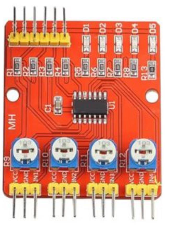
The 4 Channel IR Line Tracking Sensor Module is a versatile sensor designed for detecting lines or paths using infrared (IR) light. It is commonly used in robotics for line-following applications, where it enables robots to navigate along predefined paths with precision. The module features four independent IR sensors, allowing it to detect multiple points along a line simultaneously, making it ideal for complex navigation tasks.
Explore Projects Built with 4 Channel IR Line Tracking Sensor Module


Explore Projects Built with 4 Channel IR Line Tracking Sensor Module
Common Applications and Use Cases
- Line-following robots for educational and industrial purposes
- Automated guided vehicles (AGVs)
- Obstacle detection and avoidance systems
- Path tracking in robotic competitions
- Edge detection in conveyor belt systems
Technical Specifications
Below are the key technical details of the 4 Channel IR Line Tracking Sensor Module:
| Parameter | Specification |
|---|---|
| Operating Voltage | 3.3V - 5V DC |
| Operating Current | ≤ 60mA |
| Detection Range | 1mm - 12mm (optimal: 2mm - 8mm) |
| Output Type | Digital (High/Low) |
| Sensor Count | 4 independent IR sensors |
| Dimensions | ~70mm x 20mm x 10mm |
| Weight | ~10g |
| Operating Temperature | -10°C to 50°C |
Pin Configuration and Descriptions
The module has a total of 6 pins. Below is the pinout description:
| Pin | Name | Description |
|---|---|---|
| 1 | VCC | Power supply input (3.3V - 5V DC) |
| 2 | GND | Ground connection |
| 3 | OUT1 | Digital output for Sensor 1 (High = Line detected, Low = No line detected) |
| 4 | OUT2 | Digital output for Sensor 2 (High = Line detected, Low = No line detected) |
| 5 | OUT3 | Digital output for Sensor 3 (High = Line detected, Low = No line detected) |
| 6 | OUT4 | Digital output for Sensor 4 (High = Line detected, Low = No line detected) |
Usage Instructions
How to Use the Component in a Circuit
- Power the Module: Connect the
VCCpin to a 3.3V or 5V power source and theGNDpin to ground. - Connect Outputs: Connect the
OUT1,OUT2,OUT3, andOUT4pins to the digital input pins of a microcontroller (e.g., Arduino UNO). - Position the Module: Place the module approximately 2mm to 8mm above the surface to be tracked. Ensure the surface has a clear contrast between the line and the background (e.g., black line on a white surface).
- Read Outputs: Monitor the digital outputs. A HIGH signal indicates the presence of a line, while a LOW signal indicates no line.
Important Considerations and Best Practices
- Surface Contrast: Ensure the line and background have sufficient contrast for accurate detection.
- Ambient Light: Avoid excessive ambient light interference, as it may affect IR sensor performance.
- Distance Calibration: Adjust the height of the module for optimal detection within the specified range (2mm - 8mm).
- Power Supply: Use a stable power source to avoid fluctuations in sensor readings.
Example Code for Arduino UNO
Below is an example Arduino sketch to read the outputs of the 4 Channel IR Line Tracking Sensor Module:
// Define the pins connected to the sensor module
#define SENSOR1_PIN 2  // OUT1 connected to digital pin 2
#define SENSOR2_PIN 3  // OUT2 connected to digital pin 3
#define SENSOR3_PIN 4  // OUT3 connected to digital pin 4
#define SENSOR4_PIN 5  // OUT4 connected to digital pin 5

void setup() {
  // Initialize serial communication for debugging
  Serial.begin(9600);

  // Set sensor pins as inputs
  pinMode(SENSOR1_PIN, INPUT);
  pinMode(SENSOR2_PIN, INPUT);
  pinMode(SENSOR3_PIN, INPUT);
  pinMode(SENSOR4_PIN, INPUT);
}

void loop() {
  // Read the state of each sensor
  int sensor1State = digitalRead(SENSOR1_PIN);
  int sensor2State = digitalRead(SENSOR2_PIN);
  int sensor3State = digitalRead(SENSOR3_PIN);
  int sensor4State = digitalRead(SENSOR4_PIN);

  // Print the sensor states to the Serial Monitor
  Serial.print("Sensor 1: ");
  Serial.print(sensor1State);
  Serial.print(" | Sensor 2: ");
  Serial.print(sensor2State);
  Serial.print(" | Sensor 3: ");
  Serial.print(sensor3State);
  Serial.print(" | Sensor 4: ");
  Serial.println(sensor4State);

  // Add a small delay for readability
  delay(100);
}
Troubleshooting and FAQs
Common Issues and Solutions
No Line Detection:
- Cause: Insufficient contrast between the line and the background.
- Solution: Use a darker line on a lighter background or vice versa.
Inconsistent Readings:
- Cause: Module placed too far or too close to the surface.
- Solution: Adjust the height of the module to stay within the optimal range (2mm - 8mm).
All Sensors Always HIGH or LOW:
- Cause: Faulty wiring or power supply issues.
- Solution: Check all connections and ensure the module is powered correctly.
Interference from Ambient Light:
- Cause: Strong ambient light affecting IR sensors.
- Solution: Use the module in a controlled lighting environment or shield it from direct light.
FAQs
Q1: Can this module detect curved lines?
A1: Yes, the module can detect curved lines as long as the curve is within the range of the four sensors.
Q2: Can I use this module with a Raspberry Pi?
A2: Yes, the module can be used with a Raspberry Pi. Connect the output pins to GPIO pins and read their states using Python or other programming languages.
Q3: What is the maximum speed of a robot using this module?
A3: The maximum speed depends on the robot's design and the processing speed of the microcontroller. Ensure the robot moves slow enough for the sensors to detect the line accurately.
Q4: Can this module detect colors?
A4: No, the module is designed to detect the presence or absence of a line based on contrast, not specific colors.