How to Use DC-DC BUCK CONVERTE: Examples, Pinouts, and Specs
Introduction
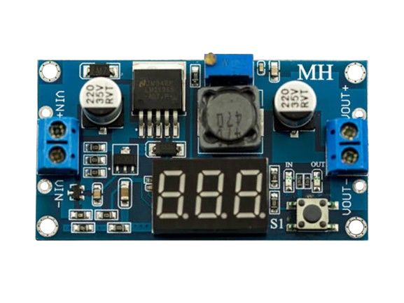
A DC-DC buck converter is a type of power converter designed to step down voltage from a higher level to a lower level while maintaining high efficiency. It achieves this by using a combination of a switching element (such as a transistor), an inductor, and a diode. The buck converter is widely used in applications where voltage regulation is critical, such as battery-powered devices, microcontroller-based systems, and portable electronics. Its ability to efficiently convert power makes it an essential component in modern electronics.
Explore Projects Built with DC-DC BUCK CONVERTE


Explore Projects Built with DC-DC BUCK CONVERTE
Common Applications
- Voltage regulation for microcontrollers and sensors
- Powering low-voltage devices from higher-voltage sources
- Battery-powered systems (e.g., laptops, smartphones, and IoT devices)
- Renewable energy systems (e.g., solar panels)
- Automotive electronics
Technical Specifications
Below are the general technical specifications for a typical DC-DC buck converter. Note that specific models may vary, so always refer to the datasheet of the exact component you are using.
Key Specifications
| Parameter | Value |
|---|---|
| Input Voltage Range | 4.5V to 40V |
| Output Voltage Range | 1.25V to 37V (adjustable) |
| Output Current | Up to 3A (depending on the model) |
| Efficiency | Up to 90% |
| Switching Frequency | 150 kHz (typical) |
| Operating Temperature | -40°C to +85°C |
Pin Configuration
The pinout of a typical DC-DC buck converter module is as follows:
| Pin Name | Description |
|---|---|
| VIN | Input voltage (connect to the power source) |
| VOUT | Output voltage (connect to the load) |
| GND | Ground (common ground for input and output) |
| ADJ (if available) | Voltage adjustment pin (for setting output voltage) |
Usage Instructions
How to Use the DC-DC Buck Converter in a Circuit
Connect the Input Voltage (VIN):
- Connect the positive terminal of your power source to the VIN pin.
- Ensure the input voltage is within the specified range of the converter.
Connect the Output Voltage (VOUT):
- Connect the positive terminal of your load to the VOUT pin.
- Ensure the load does not exceed the maximum current rating of the converter.
Connect the Ground (GND):
- Connect the ground of your power source and load to the GND pin.
Adjust the Output Voltage (if applicable):
- If the module has an adjustable output, use the onboard potentiometer or ADJ pin to set the desired output voltage.
- Use a multimeter to measure the output voltage while adjusting.
Add Capacitors (Optional):
- For improved stability, you can add input and output capacitors as recommended in the datasheet.
Important Considerations
- Heat Dissipation: Ensure proper heat dissipation, especially for high-current applications. Use a heatsink if necessary.
- Input Voltage: Always ensure the input voltage is higher than the desired output voltage.
- Load Requirements: Do not exceed the maximum current rating of the converter.
- Ripple and Noise: Use appropriate filtering capacitors to minimize output voltage ripple.
Example: Using a Buck Converter with Arduino UNO
Below is an example of how to use a DC-DC buck converter to power an Arduino UNO from a 12V power source.
Circuit Connections
- Connect the 12V power source to the VIN pin of the buck converter.
- Adjust the output voltage of the buck converter to 5V using the onboard potentiometer.
- Connect the VOUT pin of the buck converter to the 5V pin of the Arduino UNO.
- Connect the GND pin of the buck converter to the GND pin of the Arduino UNO.
Sample Code
The following Arduino code demonstrates a simple LED blink program powered by the buck converter:
// Simple LED Blink Program for Arduino UNO
// Ensure the Arduino is powered by the buck converter set to 5V

const int ledPin = 13; // Pin connected to the onboard LED

void setup() {
  pinMode(ledPin, OUTPUT); // Set the LED pin as an output
}

void loop() {
  digitalWrite(ledPin, HIGH); // Turn the LED on
  delay(1000);                // Wait for 1 second
  digitalWrite(ledPin, LOW);  // Turn the LED off
  delay(1000);                // Wait for 1 second
}
Troubleshooting and FAQs
Common Issues and Solutions
No Output Voltage:
- Check the input voltage and ensure it is within the specified range.
- Verify all connections, especially VIN, VOUT, and GND.
- Ensure the load is connected properly.
Output Voltage is Incorrect:
- Adjust the potentiometer or ADJ pin to set the correct output voltage.
- Verify the input voltage is higher than the desired output voltage.
Overheating:
- Ensure the load current does not exceed the maximum rating.
- Use a heatsink or active cooling if necessary.
High Ripple or Noise:
- Add input and output capacitors as recommended in the datasheet.
- Use shielded cables and proper grounding techniques.
FAQs
Q: Can I use a buck converter to step up voltage?
A: No, a buck converter is designed only to step down voltage. For stepping up voltage, use a boost converter.
Q: How do I calculate the efficiency of the buck converter?
A: Efficiency can be calculated using the formula:
[
\text{Efficiency} = \left( \frac{\text{Output Power}}{\text{Input Power}} \right) \times 100
]
Measure the input and output voltage and current to determine power.
Q: Can I use the buck converter with an AC power source?
A: No, the buck converter is designed for DC input only. Use a rectifier and filter circuit to convert AC to DC before using the buck converter.
By following this documentation, you can effectively use a DC-DC buck converter in your projects while ensuring optimal performance and reliability.