How to Use Infrared Proximity Sensor: Examples, Pinouts, and Specs

Introduction
An Infrared (IR) Proximity Sensor is an electronic device that detects the presence or absence of an object by measuring the infrared light reflecting off it. This sensor is widely used in various applications such as robotics, automation systems, security devices, and interactive installations. It operates by emitting an infrared signal and then receiving the reflected signal to determine the proximity of an object.
Explore Projects Built with Infrared Proximity Sensor


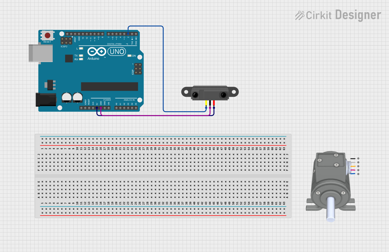
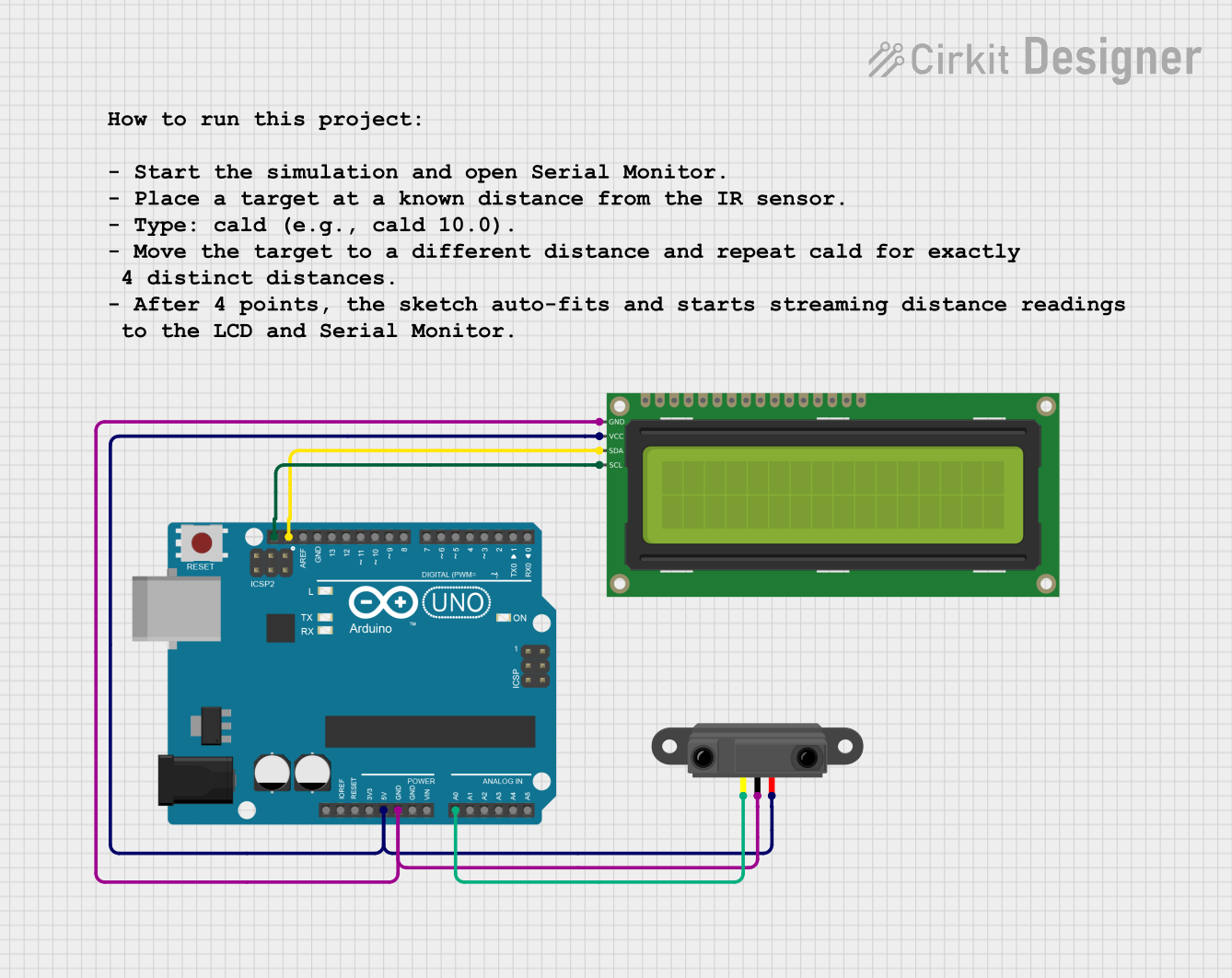
Explore Projects Built with Infrared Proximity Sensor
Technical Specifications
Key Technical Details
- Operating Voltage: Typically 3.3V to 5V
- Current Consumption: 20mA to 40mA (varies by model)
- Sensing Range: 2cm to 30cm (varies by model)
- Output Type: Digital (High or Low) or Analog (Voltage level proportional to distance)
- Response Time: < 2ms (varies by model)
- Ambient Light Resistance: Good resistance to ambient light interference
Pin Configuration and Descriptions
| Pin Number | Name | Description |
|---|---|---|
| 1 | VCC | Power supply (3.3V to 5V) |
| 2 | GND | Ground connection |
| 3 | OUT | Output signal (Digital or Analog) |
| 4 | EN | Enable pin (optional, not present on all models) |
Usage Instructions
Connecting to a Circuit
- Connect the VCC pin to the power supply (3.3V or 5V, depending on your sensor's specifications).
- Connect the GND pin to the ground of the power supply.
- Connect the OUT pin to an input pin on your microcontroller (e.g., Arduino UNO).
- If available, connect the EN pin to a digital output pin on your microcontroller to control the sensor's operation.
Important Considerations and Best Practices
- Ensure that the power supply voltage matches the sensor's operating voltage.
- Avoid exposing the sensor to direct sunlight or strong infrared sources to prevent false readings.
- Keep the sensor's lens clean and free from obstructions.
- Calibrate the sensor if necessary, according to the manufacturer's instructions.
Example Code for Arduino UNO
// Define the sensor output pin
const int sensorPin = 2;

void setup() {
  // Initialize the sensor output pin as an input
  pinMode(sensorPin, INPUT);
  // Begin serial communication at 9600 baud rate
  Serial.begin(9600);
}

void loop() {
  // Read the sensor value
  int sensorValue = digitalRead(sensorPin);
  // Print the sensor value to the serial monitor
  Serial.println(sensorValue);
  // A short delay before the next reading
  delay(100);
}
Troubleshooting and FAQs
Common Issues
- Sensor not responding: Ensure that the sensor is properly powered and that the connections are secure.
- Inconsistent readings: Check for any objects that may be intermittently reflecting IR light and causing false triggers.
- No object detection: Verify that the object's surface is not highly reflective or absorptive to IR light.
Solutions and Tips for Troubleshooting
- Double-check wiring and solder joints for any loose connections or shorts.
- Test the sensor with a known good microcontroller and power source.
- Adjust the sensor's sensitivity or range, if applicable, using onboard potentiometers.
- Shield the sensor from ambient light sources that may interfere with its operation.
FAQs
Q: Can the sensor detect transparent objects? A: It depends on the object's IR reflectivity. Some transparent materials may not reflect IR light well, making detection difficult.
Q: What is the maximum range of the sensor? A: The maximum range varies by model but is typically around 30cm.
Q: Can the sensor be used outdoors? A: While some models may be designed for outdoor use, environmental factors like sunlight can affect the sensor's performance. It's best to consult the manufacturer's specifications.
Remember to consult the specific datasheet for your Infrared Proximity Sensor model for precise information and instructions.