
How to Use BUTTONPAD-2X2: Examples, Pinouts, and Specs
 Design with BUTTONPAD-2X2 in Cirkit Designer
Introduction
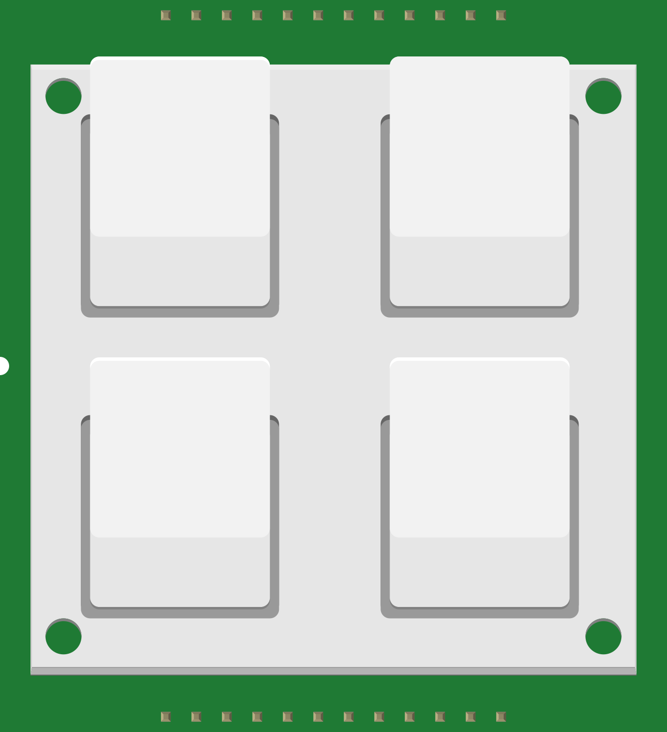
The BUTTONPAD-2X2 is a compact 2x2 matrix button pad designed for user input in electronic projects. It features four tactile buttons arranged in a grid, making it ideal for applications requiring simple and intuitive control interfaces. The matrix design allows for efficient wiring and detection of multiple button presses, making it suitable for projects like control panels, gaming devices, and menu navigation systems.
Explore Projects Built with BUTTONPAD-2X2
 Open Project in Cirkit Designer
 Open Project in Cirkit Designer
 Open Project in Cirkit Designer
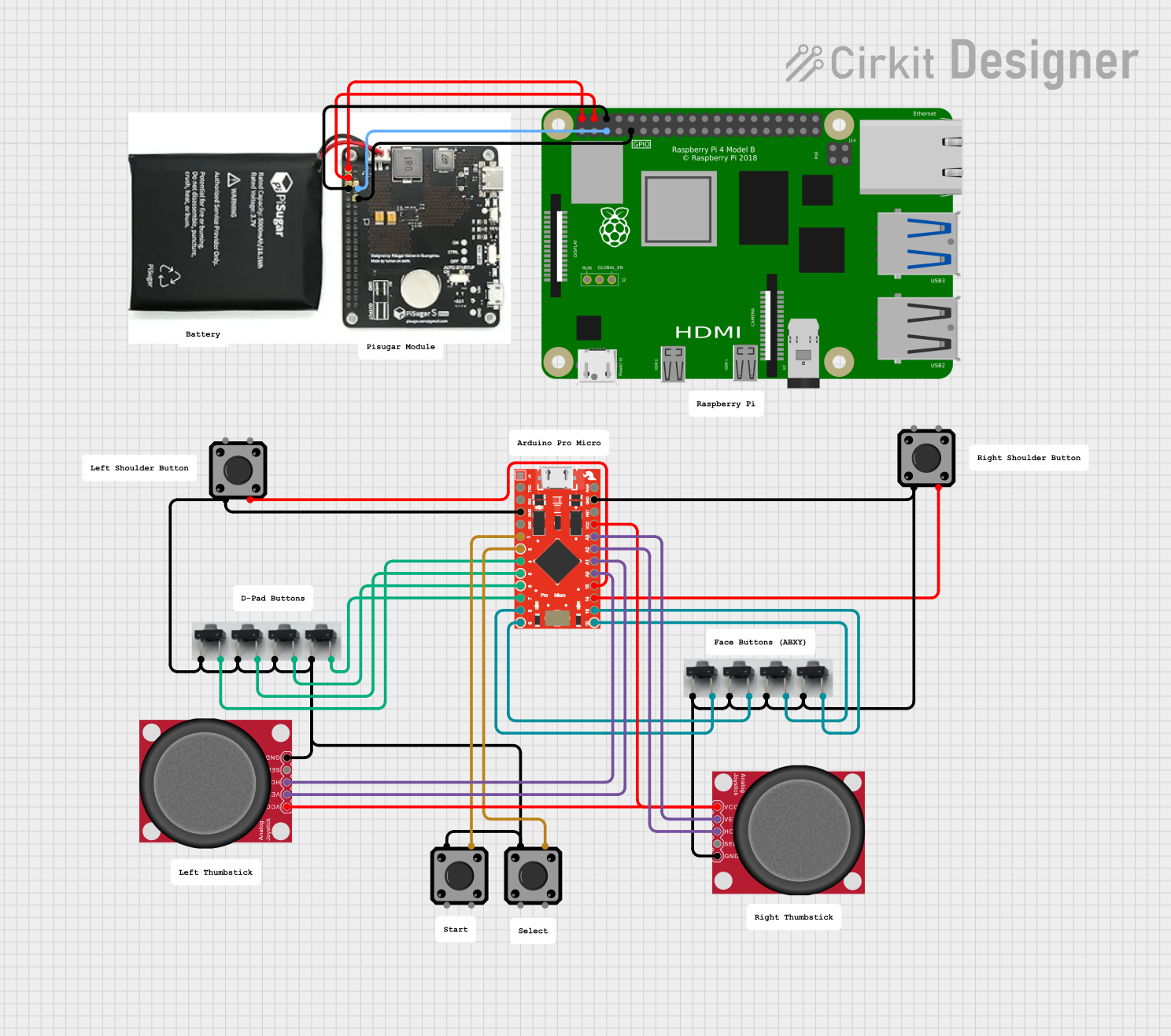 Open Project in Cirkit Designer
Explore Projects Built with BUTTONPAD-2X2
Open Project in Cirkit DesignerOpen Project in Cirkit DesignerOpen Project in Cirkit DesignerOpen Project in Cirkit DesignerCommon Applications
- DIY electronics projects
- Control panels for robotics
- Gaming controllers
- Menu navigation in embedded systems
- Prototyping user interfaces
Technical Specifications
The BUTTONPAD-2X2 is a passive component that requires external circuitry to detect button presses. Below are its key specifications:
| Parameter | Value |
|---|---|
| Number of Buttons | 4 |
| Button Layout | 2x2 matrix |
| Operating Voltage | 3.3V to 5V |
| Button Type | Tactile, momentary |
| Contact Resistance | < 100 mΩ |
| Dimensions | 1.5" x 1.5" (38mm x 38mm) |
| Pin Count | 4 pins (Row1, Row2, Col1, Col2) |
Pin Configuration
The BUTTONPAD-2X2 uses a 4-pin interface to connect the rows and columns of the button matrix. The pinout is as follows:
| Pin | Name | Description |
|---|---|---|
| 1 | Row1 | Connects to the first row of the button matrix |
| 2 | Row2 | Connects to the second row of the button matrix |
| 3 | Col1 | Connects to the first column of the button matrix |
| 4 | Col2 | Connects to the second column of the button matrix |
Usage Instructions
How to Use the BUTTONPAD-2X2 in a Circuit
The BUTTONPAD-2X2 operates as a matrix, where each button press connects a specific row to a specific column. To detect button presses:
- Connect the
Row1,Row2,Col1, andCol2pins to a microcontroller's GPIO pins. - Configure the rows as outputs and the columns as inputs (or vice versa).
- Use a scanning algorithm to detect which button is pressed:
- Set one row HIGH at a time.
- Check the column inputs to see if any button in that row is pressed.
- Repeat for all rows.
Example: Connecting to an Arduino UNO
Below is an example of how to connect and program the BUTTONPAD-2X2 with an Arduino UNO:
Circuit Connections
- Connect
Row1to Arduino pin 2. - Connect
Row2to Arduino pin 3. - Connect
Col1to Arduino pin 4. - Connect
Col2to Arduino pin 5. - Use 10kΩ pull-down resistors on the column pins to ensure stable readings.
Arduino Code
// BUTTONPAD-2X2 Example Code for Arduino UNO
// This code scans the 2x2 button matrix and prints the button states to the Serial Monitor.

const int rows[] = {2, 3}; // Row pins connected to Arduino
const int cols[] = {4, 5}; // Column pins connected to Arduino
bool buttonStates[2][2];   // Array to store button states

void setup() {
  // Initialize row pins as outputs
  for (int i = 0; i < 2; i++) {
    pinMode(rows[i], OUTPUT);
    digitalWrite(rows[i], LOW); // Set rows LOW initially
  }

  // Initialize column pins as inputs with pull-down resistors
  for (int i = 0; i < 2; i++) {
    pinMode(cols[i], INPUT);
  }

  Serial.begin(9600); // Start Serial communication
}

void loop() {
  // Scan the button matrix
  for (int row = 0; row < 2; row++) {
    // Set the current row HIGH
    digitalWrite(rows[row], HIGH);

    // Read the column states
    for (int col = 0; col < 2; col++) {
      buttonStates[row][col] = digitalRead(cols[col]);
    }

    // Set the current row LOW again
    digitalWrite(rows[row], LOW);
  }

  // Print button states to Serial Monitor
  Serial.println("Button States:");
  for (int row = 0; row < 2; row++) {
    for (int col = 0; col < 2; col++) {
      Serial.print(buttonStates[row][col]);
      Serial.print(" ");
    }
    Serial.println();
  }
  Serial.println();

  delay(200); // Small delay for stability
}
Important Considerations
- Debouncing: Mechanical buttons can produce noise or "bouncing" when pressed. Use software debouncing techniques or external capacitors to ensure stable readings.
- Pull-down Resistors: Always use pull-down resistors on the column pins to avoid floating inputs.
- Voltage Levels: Ensure the operating voltage of the BUTTONPAD-2X2 matches the microcontroller's GPIO voltage levels (typically 3.3V or 5V).
Troubleshooting and FAQs
Common Issues
No Button Press Detected
- Check the wiring and ensure all connections are secure.
- Verify that the row pins are being set HIGH during scanning.
- Ensure pull-down resistors are connected to the column pins.
Multiple Buttons Detected When Pressing One
- This may be caused by "ghosting" in the matrix. Use diodes in series with each button to prevent ghosting in larger matrices.
Unstable or Erratic Readings
- Add software debouncing to filter out noise from button presses.
- Check for loose connections or damaged components.
FAQs
Q: Can I use the BUTTONPAD-2X2 with a Raspberry Pi?
A: Yes, the BUTTONPAD-2X2 can be used with any microcontroller or single-board computer that supports GPIO pins. Ensure proper voltage levels and use pull-down resistors.
Q: How do I expand the matrix for more buttons?
A: The BUTTONPAD-2X2 is fixed at 2x2, but you can combine multiple units or use a larger matrix keypad for more buttons.
Q: Can I use this button pad for analog input?
A: No, the BUTTONPAD-2X2 is designed for digital input only. Each button acts as a simple switch.
By following this documentation, you can effectively integrate the BUTTONPAD-2X2 into your projects and troubleshoot any issues that arise.