How to Use DCDC Boost Converter: Examples, Pinouts, and Specs
Introduction
A DC-DC boost converter is a power electronic device designed to step up (increase) the input voltage to a higher output voltage while maintaining the same polarity. It achieves this by using inductors, capacitors, and switching elements to efficiently transfer energy. Boost converters are widely used in applications where a higher voltage is required from a lower voltage source, such as:
- Powering high-voltage devices from batteries (e.g., LED drivers, portable electronics)
- Renewable energy systems (e.g., solar panels, fuel cells)
- Automotive applications (e.g., electric vehicles, hybrid systems)
- Industrial and communication systems requiring voltage regulation
Explore Projects Built with DCDC Boost Converter


Explore Projects Built with DCDC Boost Converter
Technical Specifications
Below are the general technical specifications for a typical DC-DC boost converter. Note that actual values may vary depending on the specific model.
General Specifications
- Input Voltage Range: 3V to 32V
- Output Voltage Range: 5V to 35V (adjustable via potentiometer)
- Maximum Output Current: 2A (continuous), 3A (peak)
- Efficiency: Up to 95% (depending on input/output voltage and load)
- Switching Frequency: 150 kHz
- Operating Temperature: -40°C to +85°C
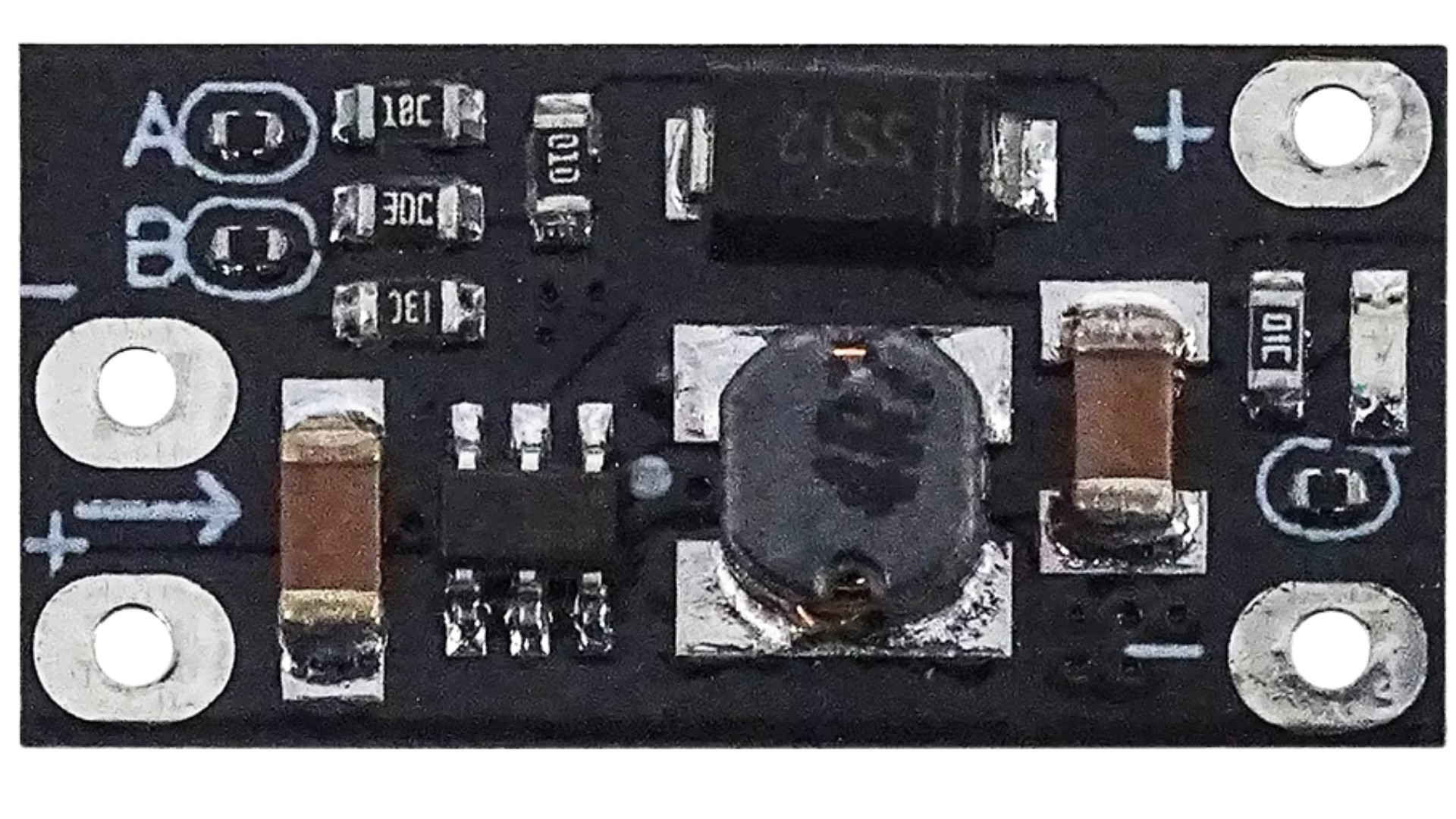
Pin Configuration and Descriptions
The DC-DC boost converter typically has four pins or terminals. Below is a table describing each pin:
| Pin/Terminal | Label | Description |
|---|---|---|
| 1 | VIN | Positive input voltage terminal. Connect to the lower voltage power source. |
| 2 | GND | Ground terminal. Connect to the negative terminal of the power source. |
| 3 | VOUT | Positive output voltage terminal. Provides the boosted voltage to the load. |
| 4 | ADJ | Adjustment pin. Used to set the output voltage via an onboard potentiometer. |
Usage Instructions
How to Use the DC-DC Boost Converter in a Circuit
Connect the Input Voltage:
- Connect the positive terminal of the power source to the
VINpin. - Connect the negative terminal of the power source to the
GNDpin.
- Connect the positive terminal of the power source to the
Set the Output Voltage:
- Use a small screwdriver to adjust the onboard potentiometer connected to the
ADJpin. - Turn clockwise to increase the output voltage or counterclockwise to decrease it.
- Use a multimeter to measure the output voltage at the
VOUTpin while adjusting.
- Use a small screwdriver to adjust the onboard potentiometer connected to the
Connect the Load:
- Connect the positive terminal of the load to the
VOUTpin. - Connect the negative terminal of the load to the
GNDpin.
- Connect the positive terminal of the load to the
Power On:
- Turn on the power source. The boost converter will step up the input voltage to the desired output voltage.
Important Considerations and Best Practices
- Input Voltage Range: Ensure the input voltage is within the specified range (e.g., 3V to 32V). Exceeding this range may damage the converter.
- Output Voltage Adjustment: Always measure the output voltage with a multimeter when adjusting the potentiometer to avoid overvoltage damage to the load.
- Current Limitations: Do not exceed the maximum output current rating (e.g., 2A continuous). Use a heatsink if the converter gets too hot under load.
- Capacitor Selection: For stable operation, ensure the input and output capacitors are of appropriate value and quality (e.g., low ESR capacitors).
- Polarity: Double-check the polarity of all connections. Reversing the input or output connections can damage the converter.
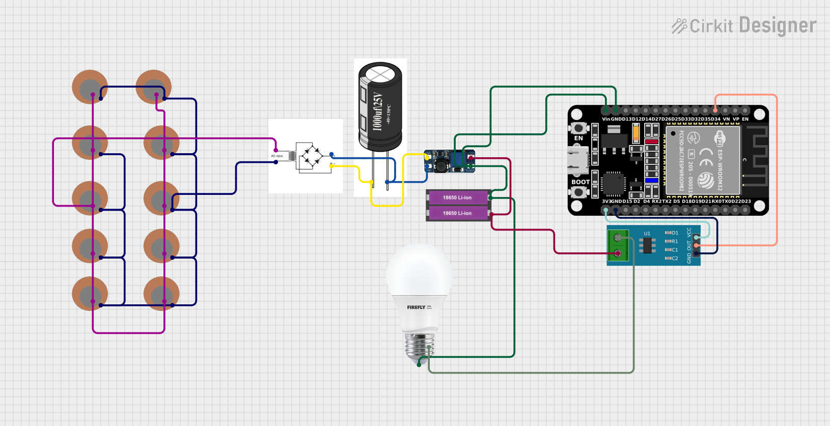
Example: Using a DC-DC Boost Converter with Arduino UNO
Below is an example of how to use a DC-DC boost converter to power an Arduino UNO from a 3.7V lithium-ion battery:
- Connect the battery's positive terminal to the
VINpin and the negative terminal to theGNDpin of the boost converter. - Adjust the potentiometer to set the output voltage to 5V (required by the Arduino UNO).
- Connect the
VOUTpin of the boost converter to the Arduino's5Vpin. - Connect the
GNDpin of the boost converter to the Arduino'sGNDpin.
Here is a simple Arduino sketch to blink an LED, powered by the boost converter:
// Simple LED blink example for Arduino UNO
// Ensure the boost converter is set to output 5V before connecting to the Arduino.

const int ledPin = 13; // Built-in LED pin on Arduino UNO

void setup() {
  pinMode(ledPin, OUTPUT); // Set the LED pin as an output
}

void loop() {
  digitalWrite(ledPin, HIGH); // Turn the LED on
  delay(1000);                // Wait for 1 second
  digitalWrite(ledPin, LOW);  // Turn the LED off
  delay(1000);                // Wait for 1 second
}
Troubleshooting and FAQs
Common Issues and Solutions
No Output Voltage:
- Cause: Incorrect wiring or insufficient input voltage.
- Solution: Verify all connections and ensure the input voltage is within the specified range.
Output Voltage Fluctuates:
- Cause: Insufficient input power or unstable load.
- Solution: Use a stable power source and ensure the load does not exceed the converter's current rating.
Converter Overheats:
- Cause: Excessive load current or poor ventilation.
- Solution: Reduce the load current or add a heatsink to the converter.
Cannot Adjust Output Voltage:
- Cause: Faulty potentiometer or incorrect adjustment procedure.
- Solution: Replace the potentiometer or ensure proper adjustment with a multimeter.
FAQs
Q: Can I use the boost converter to power a 12V device from a 5V USB source?
- A: Yes, as long as the device's current requirement does not exceed the boost converter's maximum output current.
Q: What happens if I reverse the input polarity?
- A: Most boost converters do not have reverse polarity protection, so reversing the input polarity may permanently damage the device.
Q: Can I use the boost converter with a solar panel?
- A: Yes, but ensure the solar panel's output voltage and current are within the converter's input range and power limits.
Q: How do I calculate the efficiency of the boost converter?
- A: Efficiency (%) = (Output Power / Input Power) × 100. Measure the input and output voltage and current to calculate power.
By following this documentation, you can effectively use a DC-DC boost converter in your projects while avoiding common pitfalls.