How to Use CAN Bus Shield Agrovant: Examples, Pinouts, and Specs
Introduction
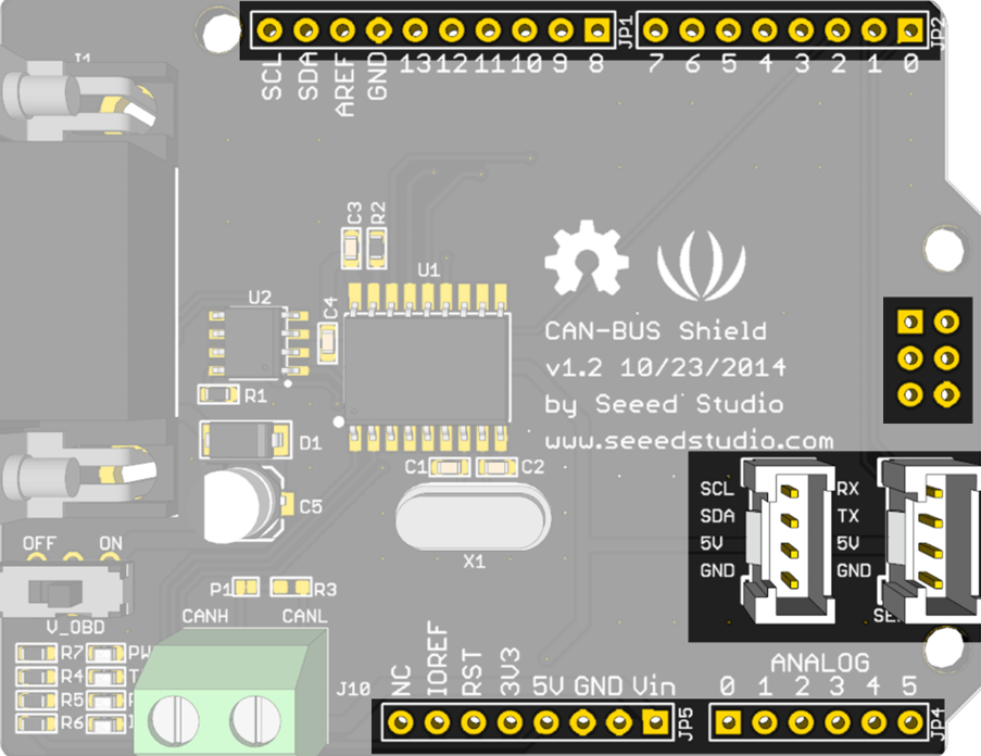
The CAN Bus Shield Agrovant, manufactured by SEEED, is a robust communication interface designed to enable microcontrollers to connect to a Controller Area Network (CAN) bus. This shield facilitates reliable and efficient data exchange, making it ideal for agricultural applications such as precision farming, machinery monitoring, and sensor data collection. Its compatibility with Arduino boards and ease of integration make it a popular choice for developers and engineers working on CAN-based systems.
Explore Projects Built with CAN Bus Shield Agrovant
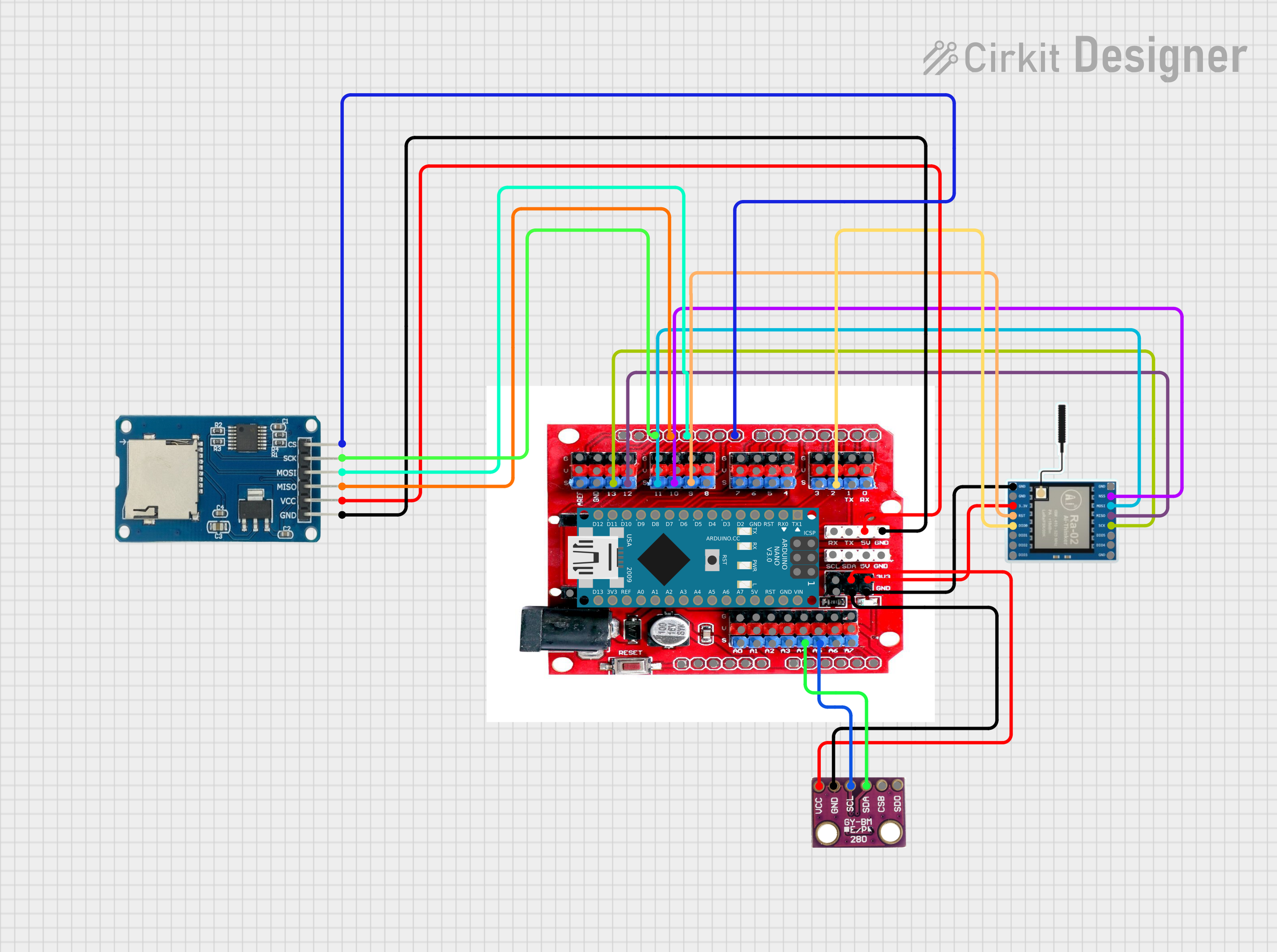
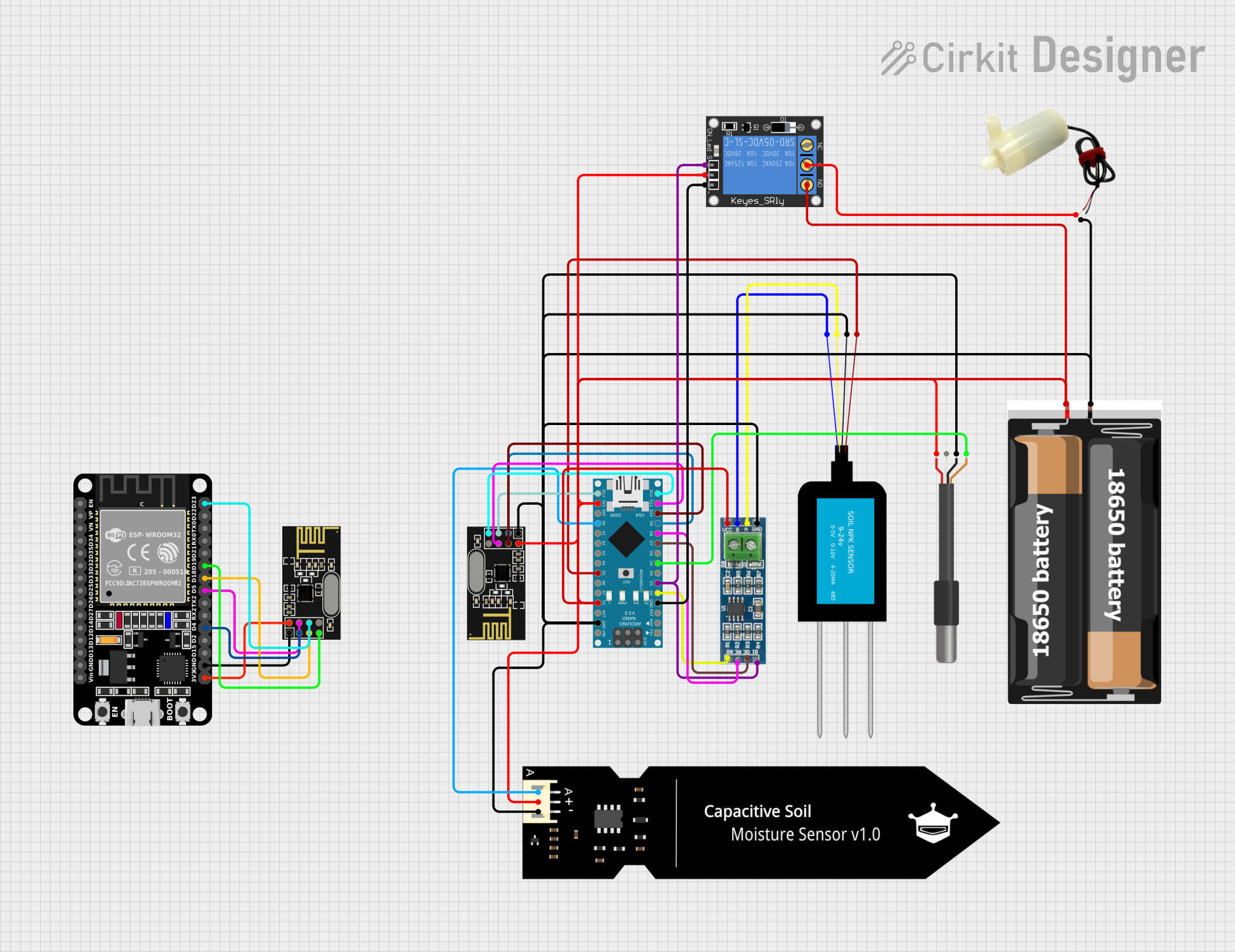
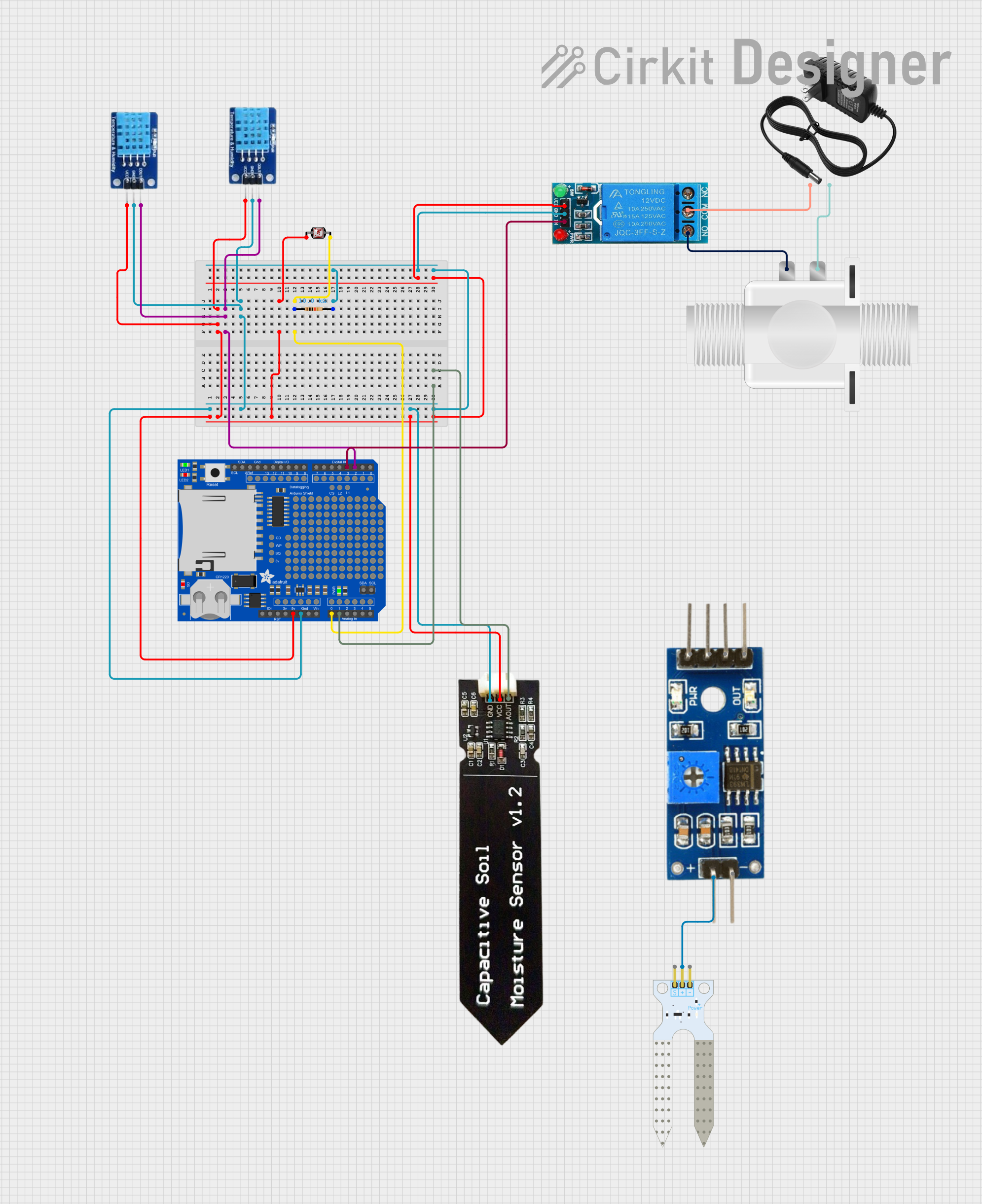
Explore Projects Built with CAN Bus Shield Agrovant
Common Applications and Use Cases
- Precision agriculture systems for monitoring and controlling equipment
- Communication between agricultural machinery (e.g., tractors, harvesters)
- Sensor networks for environmental monitoring
- Industrial automation and vehicle diagnostics
- Data logging and telemetry in CAN-based systems
Technical Specifications
The CAN Bus Shield Agrovant is built on the MCP2515 CAN controller and the MCP2551 CAN transceiver, ensuring reliable communication over the CAN bus. Below are the key technical details:
Key Technical Details
- CAN Controller: MCP2515 (SPI interface)
- CAN Transceiver: MCP2551
- Operating Voltage: 5V (from Arduino)
- Communication Speed: Up to 1 Mbps
- Connector: Standard DB9 interface for CAN bus
- Pin Compatibility: Standard Arduino Uno R3 headers
- Dimensions: 68.6mm x 53.4mm
- Operating Temperature: -40°C to 85°C
Pin Configuration and Descriptions
The CAN Bus Shield Agrovant connects to an Arduino board via its headers. Below is the pin configuration:
| Pin | Function | Description |
|---|---|---|
| D10 | SPI Chip Select (CS) | Selects the MCP2515 CAN controller for SPI communication. |
| D11 | SPI MOSI | Master Out Slave In - Data sent from Arduino to the MCP2515. |
| D12 | SPI MISO | Master In Slave Out - Data received from the MCP2515 to Arduino. |
| D13 | SPI Clock (SCK) | Clock signal for SPI communication. |
| INT | Interrupt | Indicates when the MCP2515 has data to be processed. |
| GND | Ground | Common ground connection. |
| 5V | Power Supply | Supplies 5V power to the shield. |
Usage Instructions
How to Use the Component in a Circuit
Hardware Setup:
- Attach the CAN Bus Shield Agrovant to an Arduino Uno or compatible board.
- Connect the CAN bus via the DB9 connector or the terminal block (if available).
- Ensure proper termination resistors (120Ω) are present at both ends of the CAN bus.
Software Setup:
- Install the required Arduino library for the MCP2515 (e.g., "Seeed_Arduino_CAN").
- Configure the CAN bus speed and filters in your Arduino sketch.
Basic Circuit Example:
- Connect the shield to a CAN bus network with at least one other CAN device.
- Power the Arduino and upload the code.
Important Considerations and Best Practices
- Ensure the CAN bus is properly terminated with 120Ω resistors at both ends to avoid signal reflections.
- Use shielded twisted-pair cables for the CAN bus to minimize electromagnetic interference (EMI).
- Verify that all devices on the CAN bus operate at the same baud rate.
- Avoid long cable runs to reduce signal degradation.
Example Code for Arduino UNO
Below is an example code snippet to send and receive CAN messages using the CAN Bus Shield Agrovant:
#include <SPI.h>
#include "mcp_can.h"

// Define the SPI Chip Select pin for the MCP2515
#define CAN_CS_PIN 10

// Initialize the CAN object
MCP_CAN CAN(CAN_CS_PIN);

void setup() {
  Serial.begin(115200); // Initialize serial communication for debugging
  while (!Serial);

  // Initialize the CAN bus at 500 kbps
  if (CAN.begin(MCP_ANY, CAN_500KBPS, MCP_8MHZ) == CAN_OK) {
    Serial.println("CAN Bus initialized successfully!");
  } else {
    Serial.println("Error initializing CAN Bus.");
    while (1);
  }

  // Set the CAN bus to normal mode
  CAN.setMode(MCP_NORMAL);
  Serial.println("CAN Bus set to normal mode.");
}

void loop() {
  // Example: Send a CAN message
  byte data[8] = {0x01, 0x02, 0x03, 0x04, 0x05, 0x06, 0x07, 0x08};
  if (CAN.sendMsgBuf(0x100, 0, 8, data) == CAN_OK) {
    Serial.println("Message sent successfully!");
  } else {
    Serial.println("Error sending message.");
  }

  // Example: Receive a CAN message
  if (CAN.checkReceive() == CAN_MSGAVAIL) {
    long unsigned int rxId;
    unsigned char len;
    unsigned char rxBuf[8];

    CAN.readMsgBuf(&rxId, &len, rxBuf);
    Serial.print("Received message with ID: 0x");
    Serial.println(rxId, HEX);

    Serial.print("Data: ");
    for (int i = 0; i < len; i++) {
      Serial.print(rxBuf[i], HEX);
      Serial.print(" ");
    }
    Serial.println();
  }

  delay(1000); // Wait 1 second before sending the next message
}
Troubleshooting and FAQs
Common Issues and Solutions
CAN Bus Initialization Fails:
- Cause: Incorrect SPI connection or baud rate mismatch.
- Solution: Verify the wiring and ensure all devices on the CAN bus use the same baud rate.
No Data Received:
- Cause: CAN bus not properly terminated or no other active devices on the bus.
- Solution: Check for 120Ω termination resistors and ensure at least one other device is active.
Intermittent Communication:
- Cause: EMI or long cable runs.
- Solution: Use shielded cables and minimize cable length.
Error Sending Messages:
- Cause: Bus is overloaded or incorrect message ID.
- Solution: Reduce message frequency and verify the message ID format.
FAQs
Q: Can I use this shield with boards other than Arduino Uno?
- A: Yes, the shield is compatible with other Arduino boards that have the same header layout, such as the Arduino Mega. However, you may need to adjust the SPI pins in the code.
Q: What is the maximum cable length for the CAN bus?
- A: The maximum length depends on the baud rate. For example, at 500 kbps, the maximum length is approximately 100 meters.
Q: How do I connect multiple devices to the CAN bus?
- A: Use a daisy-chain or star topology, ensuring proper termination resistors at both ends of the bus.
This documentation provides a comprehensive guide to using the CAN Bus Shield Agrovant effectively in your projects. For further assistance, refer to the SEEED official documentation or community forums.