How to Use UART TTL to RS485 Two-way Converter: Examples, Pinouts, and Specs
Introduction
The UART TTL to RS485 Two-way Converter by Elecrow is an essential device for enabling communication between devices that operate on UART TTL signals and those that use RS485 protocol. This converter is particularly useful in industrial environments where long-distance data transmission is required, as RS485 allows for robust communication over greater distances than TTL. Common applications include industrial automation systems, distributed control systems, and other scenarios where a reliable serial communication interface is needed.
Explore Projects Built with UART TTL to RS485 Two-way Converter


Explore Projects Built with UART TTL to RS485 Two-way Converter
Technical Specifications
Key Technical Details
- Operating Voltage: 3.3V to 5V
- Baud Rate: Up to 115200 bps
- Operating Temperature Range: -40°C to +85°C
- Signal Support: Full-duplex differential signal
- Maximum Cable Length: Up to 1200 meters (4000 feet) for RS485
Pin Configuration and Descriptions
| Pin Number | Name | Description |
|---|---|---|
| 1 | VCC | Power supply input (3.3V to 5V) |
| 2 | GND | Ground connection |
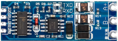
| 3 | TXD | Transmit Data input (TTL level) |
| 4 | RXD | Receive Data output (TTL level) |
| 5 | RO | Receiver Output (RS485 level) |
| 6 | RE | Receiver Enable (RS485 level) |
| 7 | DE | Driver Enable (RS485 level) |
| 8 | DI | Driver Input (RS485 level) |
| 9 | A | Non-inverting Receiver/Driver (RS485 level) |
| 10 | B | Inverting Receiver/Driver (RS485 level) |
Usage Instructions
How to Use the Component in a Circuit
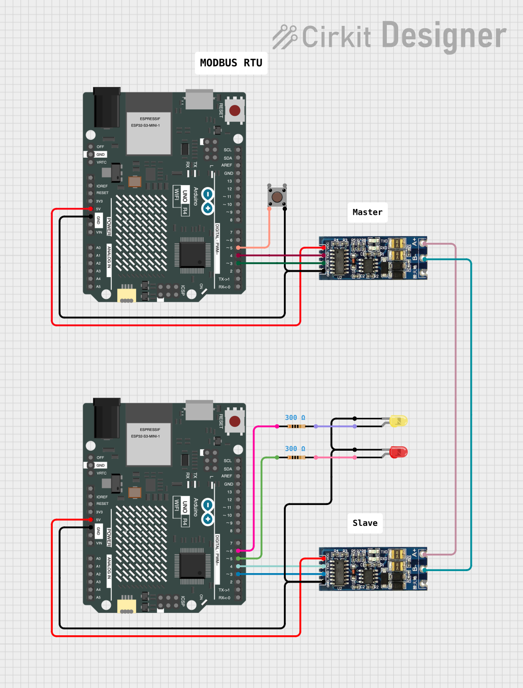
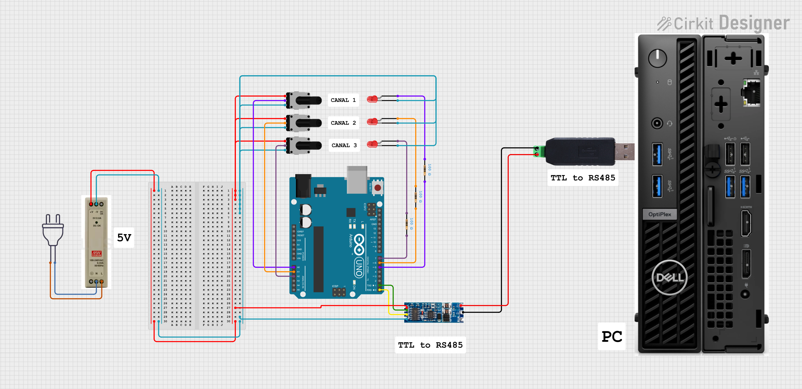
Power Connection: Connect the VCC pin to a 3.3V or 5V power supply, and the GND pin to the ground.
TTL Connection: Connect the TXD pin to the TX pin of your TTL device, and the RXD pin to the RX pin.
RS485 Connection: Connect the A and B pins to the corresponding A and B lines of the RS485 bus. Ensure that the polarity is correct to avoid communication errors.
Enabling Transmission: To enable the RS485 transmission, connect the RE and DE pins together and then to a digital output pin on your controller. Set this pin HIGH to enable transmission and LOW to enable reception.
Important Considerations and Best Practices
Termination Resistor: If the converter is located at the end of the RS485 bus, ensure that a termination resistor (typically 120 ohms) is connected across the A and B lines to prevent signal reflections.
Biasing Resistors: To ensure a defined state on the RS485 bus when all transmitters are off, it is recommended to use biasing resistors.
Cable Quality: Use twisted-pair cables for RS485 communication to reduce electromagnetic interference.
Grounding: Ensure that the ground is consistent across all devices on the RS485 network to prevent potential differences that could lead to communication errors.
Troubleshooting and FAQs
Common Issues
No Communication: Check the power supply, ensure that the TX and RX connections are correct, and that the RE and DE pins are being controlled appropriately.
Data Corruption: Verify the cable integrity, ensure proper termination and biasing, and check for correct baud rate settings.
Solutions and Tips for Troubleshooting
Signal Integrity: Use an oscilloscope to check the signal quality on the RS485 lines. Look for clean transitions and the absence of excessive noise.
Baud Rate Matching: Ensure that all devices on the RS485 network are configured to use the same baud rate.
Device Addresses: If using multiple devices on the RS485 bus, ensure that each device has a unique address and that addressing is correctly implemented in the communication protocol.
FAQs
Q: Can I use this converter with a 3.3V system? A: Yes, the converter supports operating voltages from 3.3V to 5V.
Q: How many devices can I connect to the RS485 bus? A: The RS485 standard allows up to 32 devices. However, with proper repeaters and network design, more devices can be accommodated.
Q: Is it necessary to use both RE and DE pins? A: Yes, both pins are necessary to control the direction of data flow on the RS485 bus. They are typically connected together and controlled by a single digital output from the microcontroller.
Example Code for Arduino UNO
// Define the digital pin to control RE and DE
#define RS485Control 2

// Set to HIGH for transmission, LOW for reception
#define RS485Transmit HIGH
#define RS485Receive LOW

void setup() {
  // Start the serial communication
  Serial.begin(9600);

  // Set the RS485 control pin as output
  pinMode(RS485Control, OUTPUT);

  // Set RS485 to receive mode initially
  digitalWrite(RS485Control, RS485Receive);
}

void loop() {
  // Check if data is available to read
  if (Serial.available() > 0) {
    // Read the incoming byte
    byte incomingByte = Serial.read();

    // Set RS485 to transmit mode
    digitalWrite(RS485Control, RS485Transmit);

    // Send the byte
    Serial.write(incomingByte);

    // Give the RS485 module some time to send the byte
    delay(10);

    // Set RS485 back to receive mode
    digitalWrite(RS485Control, RS485Receive);
  }

  // Implement the rest of your code here
}
This example demonstrates basic setup and data transmission for an Arduino UNO using the UART TTL to RS485 Two-way Converter. Adjust the code to fit the specific needs of your application.