How to Use CAN Bus BFF Add-On for QT Py: Examples, Pinouts, and Specs
Introduction
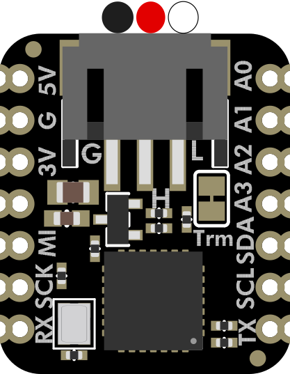
The CAN Bus BFF Add-On for QT Py is a compact and versatile board designed to add Controller Area Network (CAN) bus communication capabilities to the QT Py microcontroller. This add-on enables robust communication between multiple devices, making it ideal for automotive, industrial, and IoT applications. With its small form factor and seamless integration, the CAN Bus BFF is perfect for projects requiring reliable, high-speed data exchange in noisy environments.
Explore Projects Built with CAN Bus BFF Add-On for QT Py


Explore Projects Built with CAN Bus BFF Add-On for QT Py
Common Applications and Use Cases
- Automotive systems (e.g., engine control units, sensors, and actuators)
- Industrial automation and robotics
- IoT devices requiring inter-device communication
- Home automation systems
- Data logging and diagnostics in CAN-enabled networks
Technical Specifications
The CAN Bus BFF Add-On is built to provide reliable and efficient communication. Below are its key technical details:
Key Technical Details
- Operating Voltage: 3.3V (powered via QT Py)
- CAN Bus Transceiver: MCP25625 (integrated CAN controller and transceiver)
- Communication Protocol: CAN 2.0B
- Data Rate: Up to 1 Mbps
- Connector Type: 3-pin terminal block for CAN_H, CAN_L, and GND
- Dimensions: Matches QT Py form factor for easy stacking
- Operating Temperature Range: -40°C to 125°C
Pin Configuration and Descriptions
The CAN Bus BFF Add-On connects directly to the QT Py microcontroller. Below is the pin configuration:
| Pin Name | Description |
|---|---|
| CAN_H | High line of the CAN bus |
| CAN_L | Low line of the CAN bus |
| GND | Ground connection for the CAN bus |
| SDA | I2C data line (connected to QT Py) |
| SCL | I2C clock line (connected to QT Py) |
| INT | Interrupt pin for MCP25625 alerts |
| 3V3 | Power supply from QT Py (3.3V) |
Usage Instructions
The CAN Bus BFF Add-On is easy to use with the QT Py microcontroller. Follow these steps to integrate it into your project:
Step 1: Hardware Setup
- Attach the Add-On: Stack the CAN Bus BFF Add-On onto the QT Py microcontroller, ensuring proper alignment of the pins.
- Connect the CAN Bus: Use the 3-pin terminal block to connect the CAN_H, CAN_L, and GND lines to your CAN bus network.
- Power the System: Power the QT Py microcontroller via USB or an external power source. The add-on will draw power from the QT Py.
Step 2: Software Setup
- Install Required Libraries: Install the
Adafruit_MCP2515library in your Arduino IDE or CircuitPython environment. This library provides functions to interface with the MCP25625 CAN controller. - Configure the CAN Bus: Set the appropriate CAN bus speed (e.g., 500 kbps) to match your network.
Step 3: Example Code for Arduino UNO
Below is an example code snippet to send a CAN message using the CAN Bus BFF Add-On:
#include <Adafruit_MCP2515.h>

// Create an MCP2515 object for the CAN controller
Adafruit_MCP2515 CAN;

// Define a CAN message structure
struct CANMessage {
  uint32_t id;       // Message ID
  uint8_t data[8];   // Data payload (up to 8 bytes)
  uint8_t length;    // Length of the data payload
};

void setup() {
  Serial.begin(115200);
  while (!Serial);  // Wait for Serial Monitor to open

  // Initialize the CAN controller at 500 kbps
  if (!CAN.begin(CAN_500KBPS)) {
    Serial.println("Error: CAN controller initialization failed!");
    while (1);
  }
  Serial.println("CAN controller initialized successfully.");
}

void loop() {
  // Create a CAN message
  CANMessage message;
  message.id = 0x123;          // Set the message ID
  message.length = 2;          // Set the data length
  message.data[0] = 0xAB;      // First byte of data
  message.data[1] = 0xCD;      // Second byte of data

  // Send the CAN message
  if (CAN.sendMessage(&message)) {
    Serial.println("Message sent successfully!");
  } else {
    Serial.println("Error: Failed to send message.");
  }

  delay(1000);  // Wait 1 second before sending the next message
}
Important Considerations and Best Practices
- Termination Resistors: Ensure that your CAN bus network has 120-ohm termination resistors at both ends of the bus.
- Voltage Levels: The CAN Bus BFF operates at 3.3V logic levels. Ensure compatibility with other devices on the CAN bus.
- Bus Speed: All devices on the CAN bus must operate at the same speed (e.g., 500 kbps).
Troubleshooting and FAQs
Common Issues and Solutions
No Communication on the CAN Bus
- Cause: Incorrect bus speed or missing termination resistors.
- Solution: Verify that all devices on the CAN bus are configured to the same speed and that termination resistors are properly installed.
Error: CAN Controller Initialization Failed
- Cause: Incorrect wiring or power supply issues.
- Solution: Check the connections between the QT Py and the CAN Bus BFF. Ensure the QT Py is powered correctly.
Message Not Sent
- Cause: Bus is busy or message ID conflict.
- Solution: Check for bus congestion and ensure unique message IDs for all devices.
FAQs
Can I use this add-on with other microcontrollers?
- Yes, the CAN Bus BFF can be used with other microcontrollers that support I2C communication, but additional wiring may be required.
What is the maximum cable length for the CAN bus?
- The maximum length depends on the bus speed. For example, at 500 kbps, the maximum length is approximately 100 meters.
Does the add-on support CAN FD?
- No, the MCP25625 supports only the CAN 2.0B protocol, not CAN FD.
By following this documentation, you can successfully integrate the CAN Bus BFF Add-On for QT Py into your projects and enable reliable communication in your CAN-enabled systems.