Cirkit Designer Logo
Cirkit Designer
Your all-in-one circuit design IDE
Home / 
Component Documentation

How to Use SparkFun 9DoF Razor IMU: Examples, Pinouts, and Specs

Image of SparkFun 9DoF Razor IMU
Cirkit Designer LogoDesign with SparkFun 9DoF Razor IMU in Cirkit Designer

Introduction

The SparkFun 9DoF Razor IMU is an integrated motion sensing module that combines a 3-axis accelerometer, a 3-axis gyroscope, and a 3-axis magnetometer. This allows for precise tracking of rotational and translational movements. The Razor IMU is ideal for applications in robotics, motion analysis, and orientation tracking.

Explore Projects Built with SparkFun 9DoF Razor IMU

Use Cirkit Designer to design, explore, and prototype these projects online. Some projects support real-time simulation. Click "Open Project" to start designing instantly!
Battery-Powered Arduino UNO with BNO085 IMU and Bluetooth HC-06 for Orientation Tracking
Image of bno085: A project utilizing SparkFun 9DoF Razor IMU in a practical application
This circuit integrates an Arduino UNO with an Adafruit BNO085 9-DOF Orientation IMU and a Bluetooth HC-06 module. The Arduino reads orientation data from the IMU via I2C and transmits it over Bluetooth, powered by a 7.4V battery.
Cirkit Designer LogoOpen Project in Cirkit Designer
Arduino UNO R4 WiFi and Adafruit BNO085 IMU Fusion for Orientation Tracking
Image of Last one: A project utilizing SparkFun 9DoF Razor IMU in a practical application
This circuit consists of an Arduino UNO R4 WiFi microcontroller connected to an Adafruit BNO085 9-DOF Orientation IMU Fusion sensor. The Arduino provides power and ground to the IMU sensor and communicates with it via the I2C protocol using the SDA and SCL lines.
Cirkit Designer LogoOpen Project in Cirkit Designer
Arduino UNO R4 WiFi and Adafruit BNO085 IMU Fusion for Orientation Tracking
Image of v2: A project utilizing SparkFun 9DoF Razor IMU in a practical application
This circuit consists of an Arduino UNO R4 WiFi microcontroller connected to an Adafruit BNO085 9-DOF Orientation IMU Fusion sensor. The Arduino communicates with the IMU sensor via I2C protocol, providing power and ground connections to the sensor, enabling it to read orientation data.
Cirkit Designer LogoOpen Project in Cirkit Designer
Arduino UNO-Based IMU and Bluetooth Communication System
Image of New one: A project utilizing SparkFun 9DoF Razor IMU in a practical application
This circuit features an Arduino UNO microcontroller interfaced with a Bluetooth HC-06 module for wireless communication and an Adafruit BNO085 9-DOF Orientation IMU for motion sensing. The Arduino handles data acquisition from the IMU via I2C and communicates the data wirelessly through the Bluetooth module.
Cirkit Designer LogoOpen Project in Cirkit Designer

Explore Projects Built with SparkFun 9DoF Razor IMU

Use Cirkit Designer to design, explore, and prototype these projects online. Some projects support real-time simulation. Click "Open Project" to start designing instantly!
Image of bno085: A project utilizing SparkFun 9DoF Razor IMU in a practical application
Battery-Powered Arduino UNO with BNO085 IMU and Bluetooth HC-06 for Orientation Tracking
This circuit integrates an Arduino UNO with an Adafruit BNO085 9-DOF Orientation IMU and a Bluetooth HC-06 module. The Arduino reads orientation data from the IMU via I2C and transmits it over Bluetooth, powered by a 7.4V battery.
Cirkit Designer LogoOpen Project in Cirkit Designer
Image of Last one: A project utilizing SparkFun 9DoF Razor IMU in a practical application
Arduino UNO R4 WiFi and Adafruit BNO085 IMU Fusion for Orientation Tracking
This circuit consists of an Arduino UNO R4 WiFi microcontroller connected to an Adafruit BNO085 9-DOF Orientation IMU Fusion sensor. The Arduino provides power and ground to the IMU sensor and communicates with it via the I2C protocol using the SDA and SCL lines.
Cirkit Designer LogoOpen Project in Cirkit Designer
Image of v2: A project utilizing SparkFun 9DoF Razor IMU in a practical application
Arduino UNO R4 WiFi and Adafruit BNO085 IMU Fusion for Orientation Tracking
This circuit consists of an Arduino UNO R4 WiFi microcontroller connected to an Adafruit BNO085 9-DOF Orientation IMU Fusion sensor. The Arduino communicates with the IMU sensor via I2C protocol, providing power and ground connections to the sensor, enabling it to read orientation data.
Cirkit Designer LogoOpen Project in Cirkit Designer
Image of New one: A project utilizing SparkFun 9DoF Razor IMU in a practical application
Arduino UNO-Based IMU and Bluetooth Communication System
This circuit features an Arduino UNO microcontroller interfaced with a Bluetooth HC-06 module for wireless communication and an Adafruit BNO085 9-DOF Orientation IMU for motion sensing. The Arduino handles data acquisition from the IMU via I2C and communicates the data wirelessly through the Bluetooth module.
Cirkit Designer LogoOpen Project in Cirkit Designer

Technical Specifications

Key Technical Details

  • Accelerometer Range: ±2/±4/±8/±16g
  • Gyroscope Range: ±250/±500/±1000/±2000°/sec
  • Magnetometer Range: ±4800µT
  • Operating Voltage: 3.3V to 5V
  • Communication: I2C/SPI
  • Dimensions: 35 x 30 mm

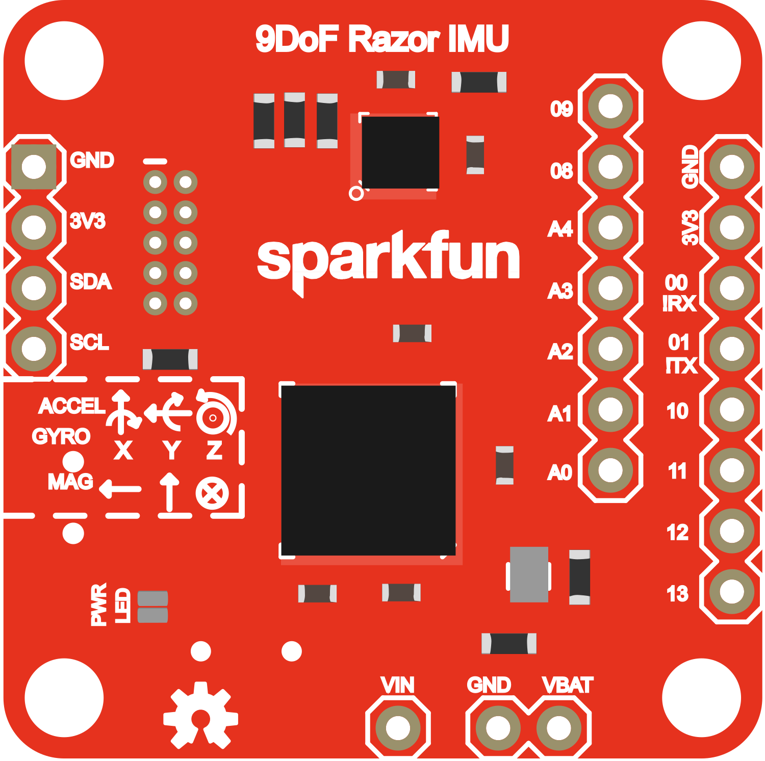
Pin Configuration and Descriptions

Pin Number Name Description
1 GND Ground connection
2 VCC Power supply (3.3V-5V)
3 SDA I2C Data Line
4 SCL I2C Clock Line
5 RXI UART Receive Pin
6 TXO UART Transmit Pin
7 SPC SPI Clock Line
8 SDO SPI Data Output
9 SDI SPI Data Input
10 CS SPI Chip Select

Usage Instructions

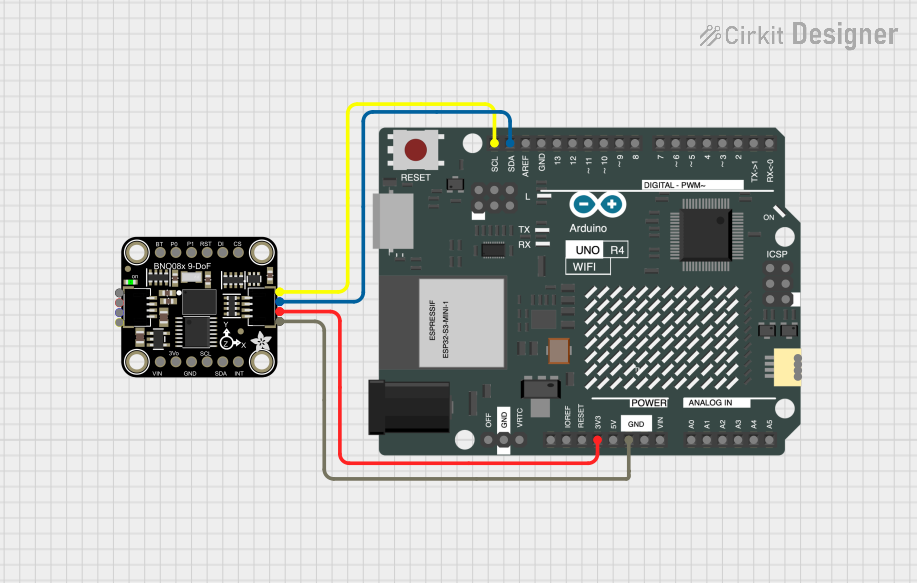
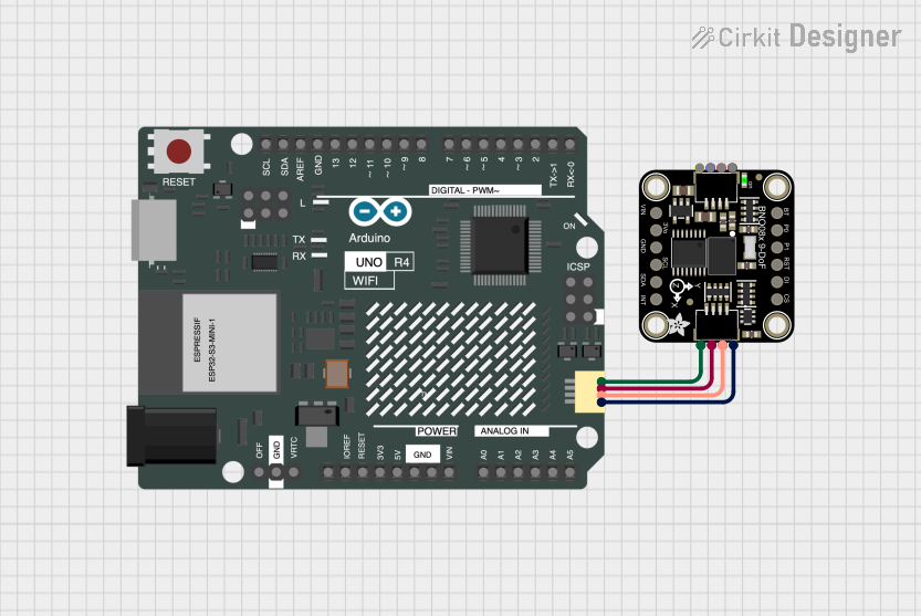
Integration with a Circuit

  1. Powering the Module: Connect the VCC pin to a 3.3V or 5V power supply and the GND pin to the ground.
  2. Communication Setup: Choose between I2C or SPI for communication and connect the respective pins to your microcontroller.
  3. Mounting: Secure the module to your application, ensuring it is firmly in place to avoid erroneous readings due to vibrations.

Best Practices

  • Calibration: Calibrate the magnetometer to account for any magnetic distortions specific to your environment.
  • Orientation: Mount the IMU in a stable orientation where it is less likely to experience sudden jolts or movements.
  • Code Libraries: Utilize existing libraries and code examples to expedite development.

Example Code for Arduino UNO

#include <Wire.h> // Include the I2C library (required)

// Razor IMU I2C address (default)
#define RAZOR_IMU_ADDR 0x68

void setup() {
  Wire.begin(); // Initialize I2C
  Serial.begin(9600); // Start serial communication at 9600 baud
}

void loop() {
  // Code to communicate with the Razor IMU and read sensor data
  // This is a placeholder for actual implementation
  Serial.println("Reading sensor data...");
  delay(1000); // Delay for demonstration purposes
}

Troubleshooting and FAQs

Common Issues

  • No Data Output: Ensure that the power supply is correctly connected and within the specified voltage range. Check the wiring of the I2C/SPI lines.
  • Inaccurate Readings: Verify that the IMU is properly calibrated and mounted securely to prevent false readings due to mechanical noise.

Solutions and Tips

  • Calibration: Perform a calibration routine at the start of your application to ensure accurate readings.
  • Firmware Updates: Keep the IMU firmware up to date to benefit from the latest improvements and bug fixes.

FAQs

Q: Can the Razor IMU be used with a 5V system? A: Yes, the IMU can be powered with a 5V supply, but ensure that the logic levels are compatible.

Q: How do I calibrate the magnetometer? A: Calibration typically involves rotating the IMU in various orientations and using software tools to compute offsets and scaling factors.

Q: What is the default communication protocol? A: The IMU supports both I2C and SPI, but I2C is commonly used and is the default in many code examples.

For further assistance, consult the SparkFun 9DoF Razor IMU forums and community resources.