How to Use Arduino: Examples, Pinouts, and Specs
Introduction
The Arduino Nano, manufactured by Smart Company (Part ID: Nano), is an open-source electronics platform designed for ease of use in both hardware and software. It is a compact, breadboard-friendly microcontroller board based on the ATmega328P or ATmega168. The Arduino Nano is widely used for building interactive projects, prototyping, and educational purposes due to its small size, versatility, and compatibility with the Arduino IDE.
Explore Projects Built with Arduino
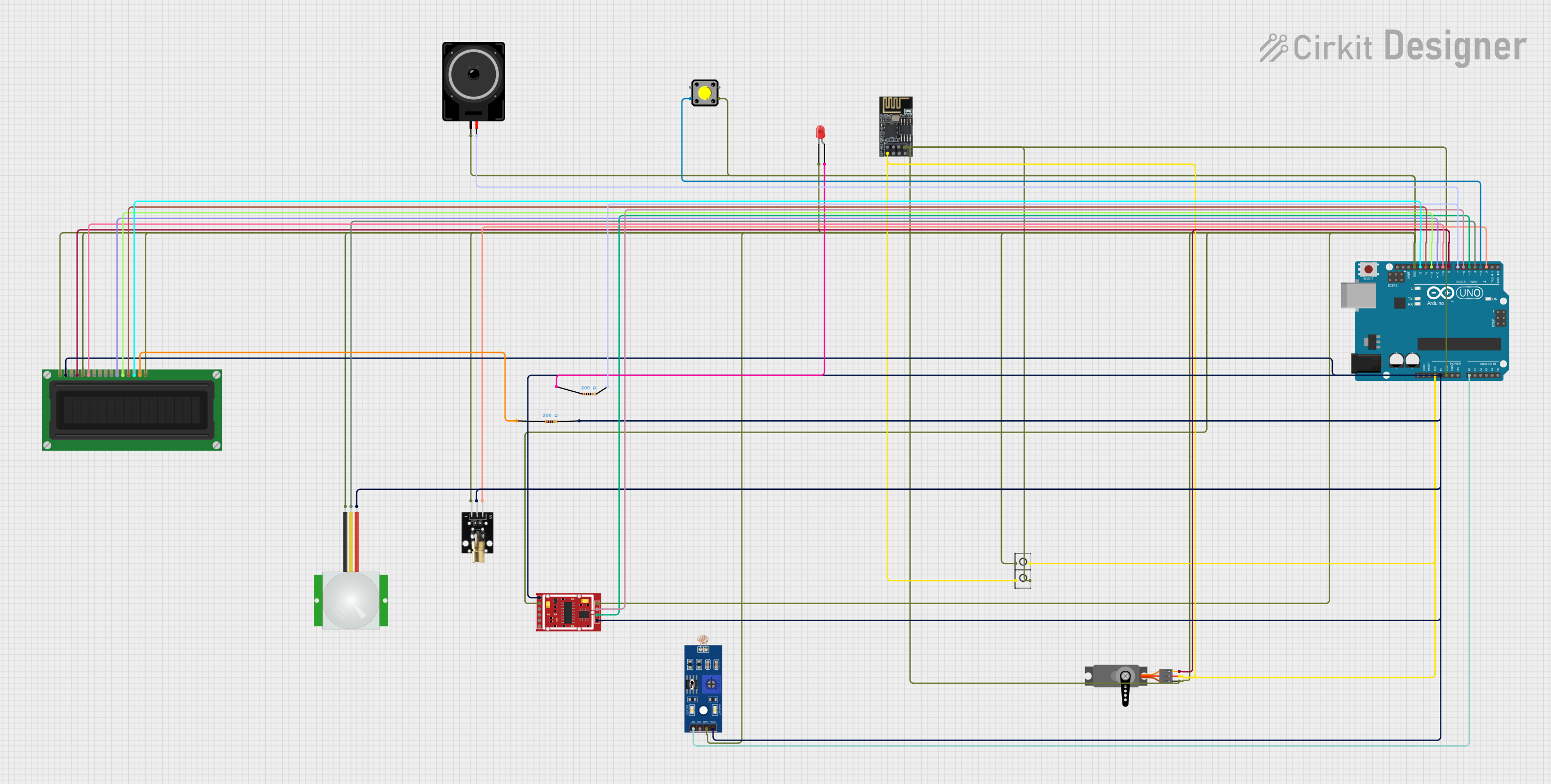

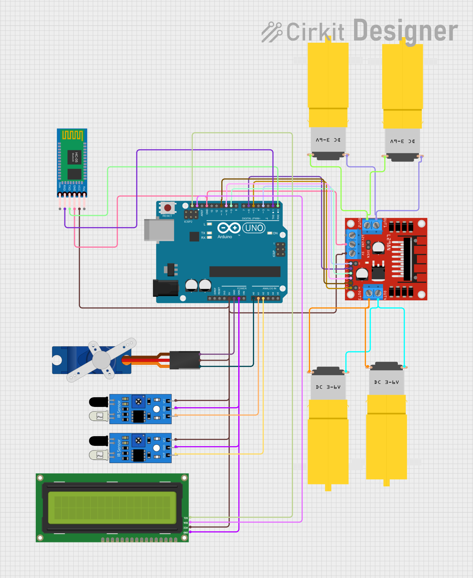
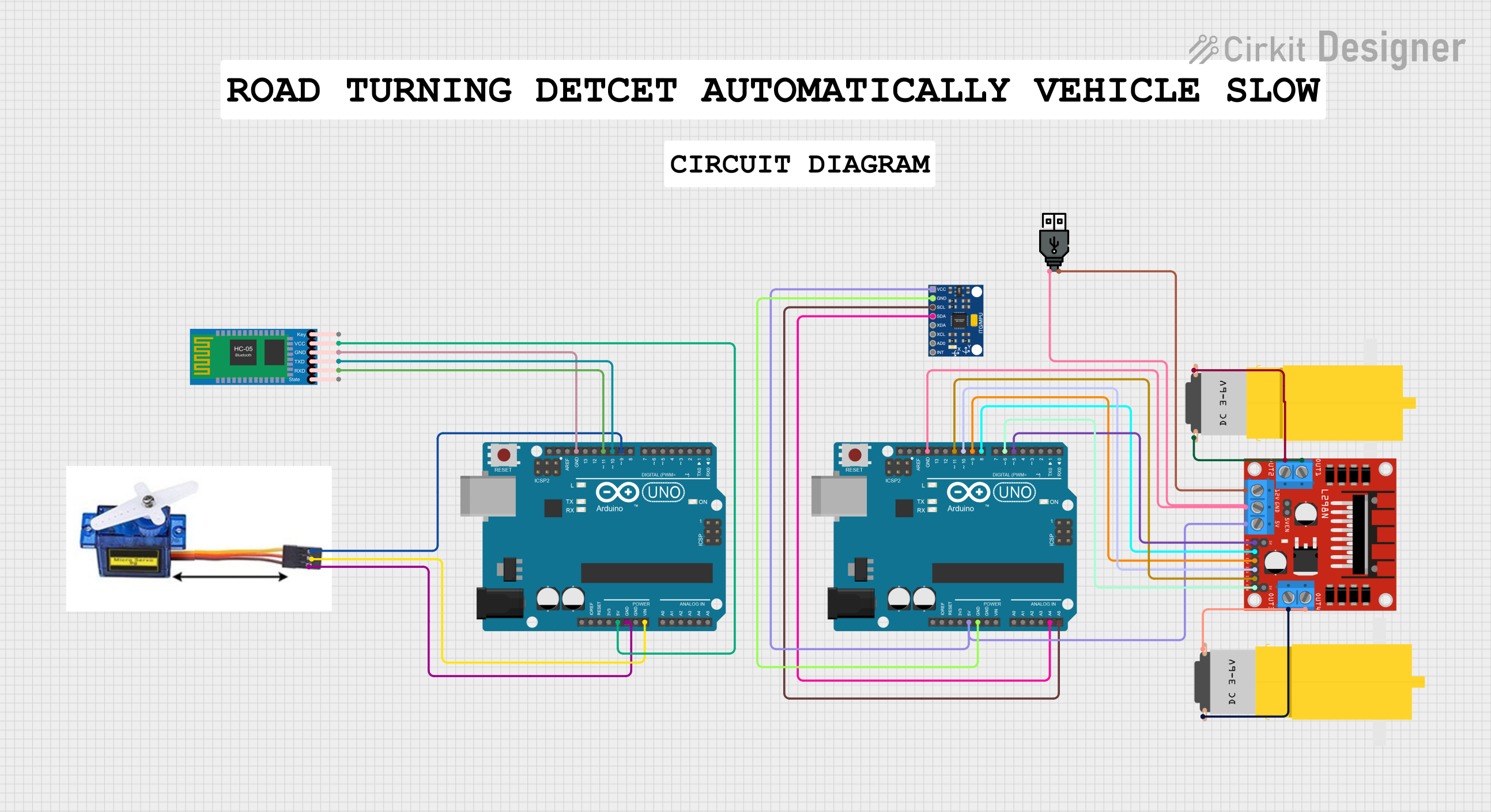
Explore Projects Built with Arduino
Common Applications and Use Cases
- Robotics and automation projects
- IoT (Internet of Things) devices
- Sensor-based systems (e.g., temperature, motion, light sensors)
- Wearable electronics
- Educational tools for learning programming and electronics
- Home automation systems
Technical Specifications
The Arduino Nano is a powerful yet compact microcontroller board. Below are its key technical details:
| Specification | Details |
|---|---|
| Microcontroller | ATmega328P (or ATmega168 in some versions) |
| Operating Voltage | 5V |
| Input Voltage (VIN) | 7-12V |
| Digital I/O Pins | 14 (6 of which support PWM output) |
| Analog Input Pins | 8 |
| DC Current per I/O Pin | 40 mA |
| Flash Memory | 32 KB (ATmega328P) or 16 KB (ATmega168), 2 KB used by bootloader |
| SRAM | 2 KB (ATmega328P) or 1 KB (ATmega168) |
| EEPROM | 1 KB (ATmega328P) or 512 bytes (ATmega168) |
| Clock Speed | 16 MHz |
| Dimensions | 18 x 45 mm |
| Weight | Approximately 7 grams |
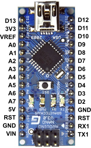
Pin Configuration and Descriptions
The Arduino Nano has a total of 30 pins. Below is a detailed description of its pinout:
| Pin | Type | Description |
|---|---|---|
| VIN | Power Input | Input voltage to the board when using an external power source (7-12V). |
| GND | Ground | Ground pins (multiple available). |
| 5V | Power Output | Regulated 5V output from the onboard regulator. |
| 3.3V | Power Output | Regulated 3.3V output (maximum current: 50 mA). |
| A0-A7 | Analog Input | Analog input pins (10-bit resolution). |
| D0-D13 | Digital I/O | Digital input/output pins. Pins D3, D5, D6, D9, D10, and D11 support PWM. |
| RX (D0) | Serial Input | UART receive pin for serial communication. |
| TX (D1) | Serial Output | UART transmit pin for serial communication. |
| RST | Reset | Resets the microcontroller. |
| ICSP | Programming | In-Circuit Serial Programming header for flashing the microcontroller firmware. |
Usage Instructions
The Arduino Nano is easy to use and program using the Arduino IDE. Follow these steps to get started:
Step 1: Install the Arduino IDE
- Download the Arduino IDE from the official Arduino website (https://www.arduino.cc/).
- Install the IDE on your computer following the provided instructions.
Step 2: Connect the Arduino Nano
- Use a USB Mini-B cable to connect the Arduino Nano to your computer.
- Open the Arduino IDE and select the correct board and port:
- Go to Tools > Board > Arduino Nano.
- Go to Tools > Port and select the port corresponding to your Arduino Nano.
Step 3: Write and Upload Code
- Write your code in the Arduino IDE. For example, the following code blinks an LED connected to pin D13:
// Blink an LED connected to pin D13
void setup() {
  pinMode(13, OUTPUT); // Set pin 13 as an output
}

void loop() {
  digitalWrite(13, HIGH); // Turn the LED on
  delay(1000);            // Wait for 1 second
  digitalWrite(13, LOW);  // Turn the LED off
  delay(1000);            // Wait for 1 second
}
- Click the Upload button in the Arduino IDE to upload the code to the Arduino Nano.
Important Considerations and Best Practices
- Ensure the correct board and port are selected in the Arduino IDE before uploading code.
- Use a stable power source to avoid unexpected resets or malfunctions.
- Avoid exceeding the maximum current ratings for I/O pins (40 mA per pin).
- Use pull-up or pull-down resistors for input pins to prevent floating states.
- When using external power, connect it to the VIN pin (7-12V) and ensure proper grounding.
Troubleshooting and FAQs
Common Issues and Solutions
The Arduino Nano is not detected by the computer.
- Ensure the USB cable is functional and properly connected.
- Install the necessary USB drivers for the Arduino Nano.
- Try a different USB port or cable.
Error: "avrdude: stk500_getsync() not in sync."
- Check that the correct board and port are selected in the Arduino IDE.
- Ensure the Arduino Nano is properly connected and powered.
The uploaded code is not working as expected.
- Verify the wiring and connections in your circuit.
- Check for syntax errors or logical issues in your code.
The Arduino Nano resets unexpectedly.
- Ensure the power supply is stable and within the recommended voltage range.
- Avoid drawing excessive current from the I/O pins.
FAQs
Q: Can I power the Arduino Nano with a battery?
A: Yes, you can power the Arduino Nano using a battery. Connect the battery's positive terminal to the VIN pin and the negative terminal to GND. Ensure the voltage is within the range of 7-12V.
Q: How do I use the analog pins on the Arduino Nano?
A: The analog pins (A0-A7) can read analog signals (0-5V) and convert them to a 10-bit digital value (0-1023). Use the analogRead() function in your code to read values from these pins.
Q: Can I use the Arduino Nano for wireless communication?
A: Yes, you can use external modules like Bluetooth (e.g., HC-05), Wi-Fi (e.g., ESP8266), or RF modules to enable wireless communication with the Arduino Nano.
Q: What is the difference between the Arduino Nano and Arduino Uno?
A: The Arduino Nano is smaller and breadboard-friendly, while the Arduino Uno is larger and has a standard USB-B connector. Both use the same microcontroller (ATmega328P) and are functionally similar.
By following this documentation, you can effectively use the Arduino Nano for a wide range of projects and applications.