
How to Use PocketBeagle: Examples, Pinouts, and Specs
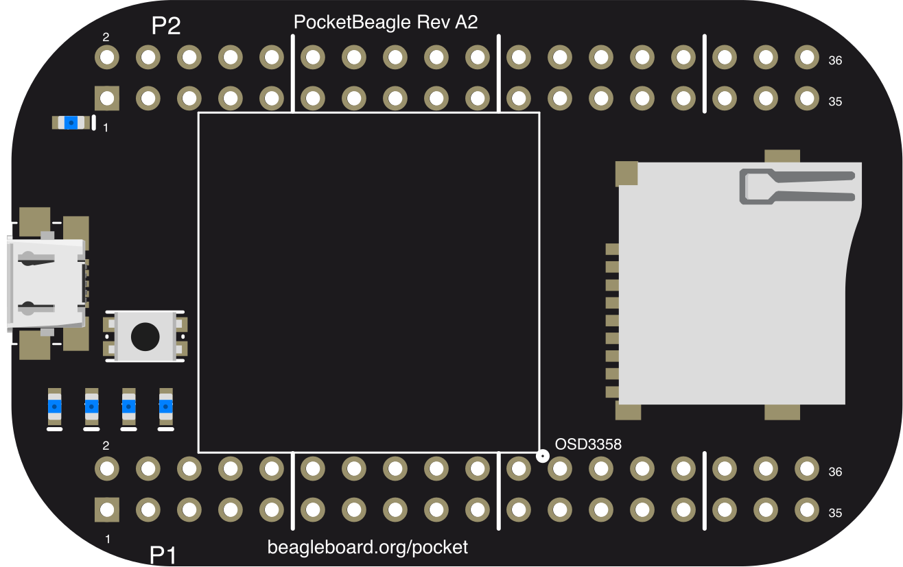
 Design with PocketBeagle in Cirkit Designer
Introduction
The PocketBeagle (Manufacturer Part ID: PocketBeagle A2) is a compact, low-power single-board computer developed by the BeagleBoard.org Foundation. It is designed for embedded applications and features a BeagleBone-compatible architecture. Powered by a 1GHz ARM Cortex-A8 processor, the PocketBeagle offers a versatile platform for developers, hobbyists, and engineers to create innovative projects.
Explore Projects Built with PocketBeagle
 Open Project in Cirkit Designer
 Open Project in Cirkit Designer
 Open Project in Cirkit Designer
 Open Project in Cirkit Designer
Explore Projects Built with PocketBeagle
Open Project in Cirkit DesignerOpen Project in Cirkit DesignerOpen Project in Cirkit DesignerOpen Project in Cirkit DesignerCommon Applications and Use Cases
- IoT (Internet of Things) devices
- Robotics and automation systems
- Wearable technology
- Educational tools for learning embedded systems
- Prototyping and product development
- Data logging and sensor interfacing
Technical Specifications
The PocketBeagle is a powerful yet compact board with the following key specifications:
Key Technical Details
| Specification | Details |
|---|---|
| Processor | 1GHz ARM Cortex-A8 (TI Sitara AM3358) |
| Co-processor | 200MHz Programmable Real-Time Unit (PRU) |
| RAM | 512MB DDR3L |
| Storage | microSD card slot (user-provided) |
| GPIO Pins | 72 pins (3.3V logic level) |
| USB | USB 2.0 OTG (micro-USB) |
| Power Supply | 5V via micro-USB |
| Dimensions | 56mm x 35mm |
| Operating System | Linux-based (Debian, Ubuntu, etc.) |
| Power Consumption | ~100mA (idle), varies with peripherals |
Pin Configuration and Descriptions
The PocketBeagle features two 36-pin headers (P1 and P2) for GPIO and peripheral connections. Below is a summary of the pin configuration:
P1 Header Pinout
| Pin Number | Name | Description | Voltage Level |
|---|---|---|---|
| P1.1 | GND | Ground | 0V |
| P1.2 | VOUT | Power output | 3.3V |
| P1.3 | GPIO_50 | General-purpose I/O | 3.3V |
| P1.4 | GPIO_51 | General-purpose I/O | 3.3V |
| ... | ... | ... | ... |
P2 Header Pinout
| Pin Number | Name | Description | Voltage Level |
|---|---|---|---|
| P2.1 | GND | Ground | 0V |
| P2.2 | VOUT | Power output | 3.3V |
| P2.3 | GPIO_60 | General-purpose I/O | 3.3V |
| P2.4 | GPIO_61 | General-purpose I/O | 3.3V |
| ... | ... | ... | ... |
For a complete pinout, refer to the official PocketBeagle documentation.
Usage Instructions
How to Use the PocketBeagle in a Circuit
- Powering the Board: Connect the PocketBeagle to a 5V power source using the micro-USB port.
- Booting the OS: Insert a microSD card with a pre-installed Linux distribution (e.g., Debian) into the microSD card slot.
- Connecting Peripherals: Use the GPIO pins on the P1 and P2 headers to interface with sensors, actuators, or other devices.
- Programming: Access the board via SSH or a serial terminal to write and execute code.
Important Considerations and Best Practices
- Voltage Levels: Ensure all connected peripherals operate at 3.3V logic levels to avoid damaging the board.
- Static Protection: Handle the board with care to prevent electrostatic discharge (ESD) damage.
- Cooling: While the PocketBeagle is low-power, consider passive cooling if running intensive tasks for extended periods.
- Software Updates: Regularly update the operating system and software packages for optimal performance and security.
Example: Blinking an LED with Arduino IDE
The PocketBeagle can be programmed using the Arduino IDE. Below is an example of blinking an LED connected to GPIO_50 (P1.3):
// Include the necessary library for PocketBeagle GPIO
#include <Adafruit_BBIO_GPIO.h>

// Define the GPIO pin for the LED
#define LED_PIN "P1_3"

void setup() {
  // Set the LED pin as an output
  pinMode(LED_PIN, OUTPUT);
}

void loop() {
  // Turn the LED on
  digitalWrite(LED_PIN, HIGH);
  delay(1000); // Wait for 1 second

  // Turn the LED off
  digitalWrite(LED_PIN, LOW);
  delay(1000); // Wait for 1 second
}
Troubleshooting and FAQs
Common Issues and Solutions
Board Does Not Power On
- Ensure the micro-USB cable is properly connected to a 5V power source.
- Verify that the power source provides sufficient current (at least 500mA).
No Output on Serial Terminal
- Check the baud rate (typically 115200) in your terminal software.
- Ensure the correct serial port is selected.
GPIO Pins Not Responding
- Confirm that the correct pin number is used in your code.
- Verify that the connected peripheral operates at 3.3V logic levels.
Overheating
- Avoid running high-power peripherals directly from the board.
- Use a heatsink or improve ventilation if necessary.
FAQs
Q: Can I power the PocketBeagle using a battery?
A: Yes, you can use a 5V battery pack connected to the micro-USB port. Ensure the battery provides sufficient current.
Q: What operating systems are supported?
A: The PocketBeagle supports Linux-based distributions such as Debian, Ubuntu, and custom builds.
Q: How do I reset the board?
A: Press and hold the reset button located on the board for a few seconds to reboot the system.
Q: Can I use the PocketBeagle for real-time applications?
A: Yes, the onboard PRU (Programmable Real-Time Unit) allows for real-time processing tasks.
For additional support, visit the BeagleBoard.org PocketBeagle page.