How to Use 400V 100A V/C Sensor: Examples, Pinouts, and Specs
Introduction
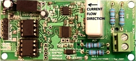
The 400V 100A V/C Sensor (Part ID: VVM312), manufactured by Vajravegha Mobility, is a high-performance voltage and current sensor designed for monitoring electrical parameters in a wide range of applications. This sensor is capable of measuring voltages up to 400V and currents up to 100A, making it ideal for use in power systems, renewable energy setups, battery management systems, and industrial automation.
Explore Projects Built with 400V 100A V/C Sensor

Explore Projects Built with 400V 100A V/C Sensor
Common Applications
- Battery management systems (BMS) for electric vehicles and energy storage systems
- Solar power monitoring and inverter systems
- Industrial equipment and motor control
- Power supply monitoring and fault detection
- IoT-based energy monitoring solutions
Technical Specifications
Key Specifications
| Parameter | Value |
|---|---|
| Voltage Measurement Range | 0V to 400V DC |
| Current Measurement Range | 0A to 100A DC |
| Accuracy | ±1% |
| Output Signal | Analog (0-5V) |
| Supply Voltage | 5V DC |
| Operating Temperature | -20°C to 85°C |
| Isolation Voltage | 2.5kV |
| Dimensions | 50mm x 30mm x 20mm |
| Weight | 25g |
Pin Configuration
The VVM312 sensor has a 5-pin interface for easy integration into circuits. The pinout is as follows:
| Pin Number | Name | Description |
|---|---|---|
| 1 | VCC | Power supply input (5V DC) |
| 2 | GND | Ground |
| 3 | V_OUT | Voltage measurement output (analog signal) |
| 4 | I_OUT | Current measurement output (analog signal) |
| 5 | NC | Not connected (leave unconnected) |
Usage Instructions
How to Use the Component in a Circuit
- Power Supply: Connect the VCC pin to a regulated 5V DC power source and the GND pin to the ground of your circuit.
- Voltage Measurement: Connect the voltage source to be measured across the sensor's input terminals. The sensor outputs an analog voltage proportional to the measured voltage on the V_OUT pin.
- Current Measurement: Pass the current-carrying conductor through the sensor's current-sensing loop. The sensor outputs an analog voltage proportional to the measured current on the I_OUT pin.
- Signal Reading: Use an ADC (Analog-to-Digital Converter) or a microcontroller (e.g., Arduino UNO) to read the analog signals from V_OUT and I_OUT.
Important Considerations
- Ensure the input voltage and current do not exceed the sensor's maximum ratings (400V and 100A).
- Use proper isolation techniques when working with high voltages to ensure safety.
- Place the sensor in a well-ventilated area to avoid overheating during prolonged use.
- For accurate readings, calibrate the sensor as per the manufacturer's guidelines.
Example: Connecting to an Arduino UNO
Below is an example of how to interface the VVM312 sensor with an Arduino UNO to measure voltage and current:
// Define the analog input pins for voltage and current
const int voltagePin = A0; // Pin connected to V_OUT
const int currentPin = A1; // Pin connected to I_OUT

void setup() {
  Serial.begin(9600); // Initialize serial communication
}

void loop() {
  // Read the analog values from the sensor
  int voltageRaw = analogRead(voltagePin);
  int currentRaw = analogRead(currentPin);

  // Convert the raw ADC values to actual voltage and current
  // Assuming a 10-bit ADC (0-1023) and 5V reference voltage
  float measuredVoltage = (voltageRaw / 1023.0) * 400.0; // Scale to 400V range
  float measuredCurrent = (currentRaw / 1023.0) * 100.0; // Scale to 100A range

  // Print the measured values to the Serial Monitor
  Serial.print("Voltage: ");
  Serial.print(measuredVoltage);
  Serial.println(" V");

  Serial.print("Current: ");
  Serial.print(measuredCurrent);
  Serial.println(" A");

  delay(1000); // Wait for 1 second before the next reading
}
Notes:
- Ensure the Arduino's ADC reference voltage is set to 5V for accurate readings.
- Use appropriate scaling factors if the sensor's output range differs from the ADC input range.
Troubleshooting and FAQs
Common Issues and Solutions
No Output Signal
- Cause: Incorrect wiring or insufficient power supply.
- Solution: Verify all connections and ensure the sensor is powered with 5V DC.
Inaccurate Readings
- Cause: Calibration not performed or external interference.
- Solution: Calibrate the sensor as per the manufacturer's instructions and minimize noise sources near the sensor.
Overheating
- Cause: Prolonged operation at maximum ratings or poor ventilation.
- Solution: Operate within recommended limits and ensure proper airflow around the sensor.
Arduino Reads Constant Values
- Cause: Faulty ADC configuration or incorrect scaling in the code.
- Solution: Check the Arduino code for correct ADC setup and scaling factors.
FAQs
Q1: Can this sensor measure AC voltage and current?
A1: No, the VVM312 is designed for DC voltage and current measurement only.
Q2: What is the output signal range of the sensor?
A2: The sensor outputs an analog signal in the range of 0-5V, proportional to the measured voltage and current.
Q3: Is the sensor suitable for outdoor use?
A3: The sensor is not weatherproof. Use it in a controlled indoor environment or within a protective enclosure for outdoor applications.
Q4: How do I calibrate the sensor?
A4: Refer to the manufacturer's calibration procedure, which typically involves comparing the sensor's output with a known reference and adjusting the scaling factors in your code.
Q5: Can I use this sensor with a 3.3V microcontroller?
A5: Yes, but you will need a voltage divider or level shifter to scale the sensor's 5V output to the 3.3V input range of the microcontroller.