How to Use Relay 5V (250V, 30A): Examples, Pinouts, and Specs
Introduction
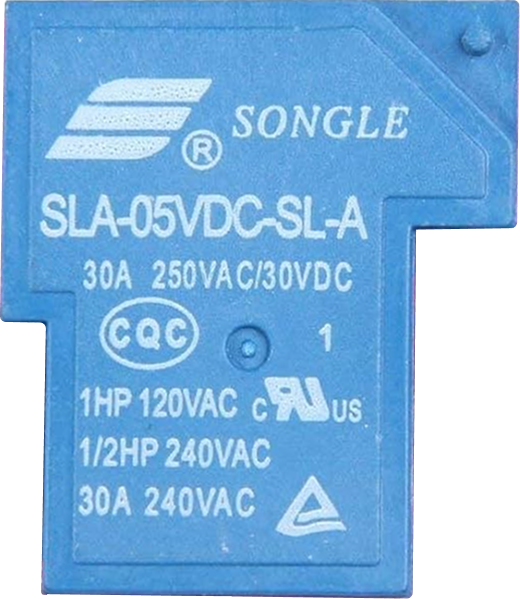
The Relay 5V (250V, 30A) is an electromechanical switch designed to control high-power devices using a low-power control signal. It operates with a 5V DC signal to toggle the connection of circuits carrying up to 250V AC or DC at a maximum current of 30A. This makes it ideal for applications requiring isolation between the control circuit and the high-power load.
Explore Projects Built with Relay 5V (250V, 30A)


Explore Projects Built with Relay 5V (250V, 30A)
Common Applications and Use Cases
- Home automation systems (e.g., controlling lights, fans, or appliances)
- Industrial equipment control
- Motor control circuits
- Power distribution systems
- IoT projects requiring high-power switching
Technical Specifications
Key Technical Details
- Control Voltage (Coil Voltage): 5V DC
- Operating Current (Coil): ~70-100mA
- Contact Voltage Rating: Up to 250V AC or DC
- Contact Current Rating: Up to 30A
- Relay Type: SPDT (Single Pole Double Throw) or SPST (Single Pole Single Throw), depending on the model
- Isolation: Electrical isolation between control and load circuits
- Switching Mechanism: Electromechanical
- Response Time: Typically 5-15ms
- Lifetime: ~100,000 operations (mechanical)
Pin Configuration and Descriptions
The relay typically has 5 pins for SPDT models. Below is the pin configuration:
| Pin Name | Description |
|---|---|
| Coil+ | Positive terminal of the relay coil (connect to 5V DC control signal). |
| Coil- | Negative terminal of the relay coil (connect to ground). |
| Common (COM) | Common terminal for the load circuit. |
| Normally Open (NO) | Open circuit when the relay is inactive; closes when the relay is activated. |
| Normally Closed (NC) | Closed circuit when the relay is inactive; opens when the relay is activated. |
Note: For SPST relays, only the COM and NO pins are present.
Usage Instructions
How to Use the Relay in a Circuit
Power the Relay Coil:
- Connect the Coil+ pin to a 5V DC control signal (e.g., from a microcontroller or power supply).
- Connect the Coil- pin to ground.
Connect the Load Circuit:
- Identify whether you want the load to be connected to the Normally Open (NO) or Normally Closed (NC) terminal.
- Connect one side of the load to the Common (COM) pin.
- Connect the other side of the load to the NO or NC pin, depending on your desired behavior.
Control the Relay:
- Apply a 5V signal to the Coil+ pin to activate the relay and switch the load circuit.
Important Considerations and Best Practices
- Use a Flyback Diode: Always connect a flyback diode (e.g., 1N4007) across the relay coil terminals to protect the control circuit from voltage spikes caused by the relay's inductive load.
- Avoid Overloading: Ensure the load does not exceed the relay's maximum voltage (250V) or current (30A) ratings.
- Isolation: Use optocouplers or transistor drivers if the control circuit cannot directly supply the required current for the relay coil.
- Heat Dissipation: For high-current loads, ensure proper ventilation or heat dissipation to prevent overheating.
Example: Connecting to an Arduino UNO
Below is an example of how to control the relay using an Arduino UNO:
// Define the relay control pin
const int relayPin = 7; // Connect this pin to the Coil+ terminal of the relay

void setup() {
  pinMode(relayPin, OUTPUT); // Set the relay pin as an output
  digitalWrite(relayPin, LOW); // Ensure the relay is off initially
}

void loop() {
  // Turn the relay on
  digitalWrite(relayPin, HIGH); // Activates the relay
  delay(5000); // Keep the relay on for 5 seconds

  // Turn the relay off
  digitalWrite(relayPin, LOW); // Deactivates the relay
  delay(5000); // Keep the relay off for 5 seconds
}
Note: Use a transistor (e.g., 2N2222) or relay driver module if the Arduino cannot supply sufficient current to the relay coil.
Troubleshooting and FAQs
Common Issues and Solutions
Relay Not Activating:
- Cause: Insufficient control voltage or current.
- Solution: Verify that the control signal is 5V and can supply at least 70-100mA. Use a transistor driver if necessary.
Load Not Switching:
- Cause: Incorrect wiring of the load circuit.
- Solution: Double-check the connections to the COM, NO, and NC pins.
Voltage Spikes Damaging the Circuit:
- Cause: Lack of a flyback diode across the relay coil.
- Solution: Install a flyback diode (e.g., 1N4007) across the Coil+ and Coil- terminals.
Relay Overheating:
- Cause: Load exceeds the relay's current rating.
- Solution: Ensure the load does not exceed 30A. Use a relay with a higher current rating if needed.
FAQs
Q: Can I use this relay with a 3.3V control signal?
A: No, the relay requires a 5V control signal. Use a level shifter or transistor driver to step up the control voltage.Q: Is the relay suitable for DC loads?
A: Yes, the relay can handle both AC and DC loads up to 250V.Q: How do I know if the relay is activated?
A: Many relay modules include an LED indicator that lights up when the relay is activated. If using a bare relay, you can measure continuity between the COM and NO pins.Q: Can I control multiple relays with one microcontroller?
A: Yes, but ensure the microcontroller can supply sufficient current or use relay driver modules for each relay.