How to Use L6470: Examples, Pinouts, and Specs
Introduction
The L6470, also known as "dSPIN," is a fully integrated microstepping motor driver with a built-in microcontroller and advanced motion control capabilities. It is designed to drive bipolar stepper motors in various applications, including robotics, precision positioning, and automation systems. The L6470 simplifies the implementation of complex motor control functions and provides a high degree of flexibility through programmable parameters.
Explore Projects Built with L6470


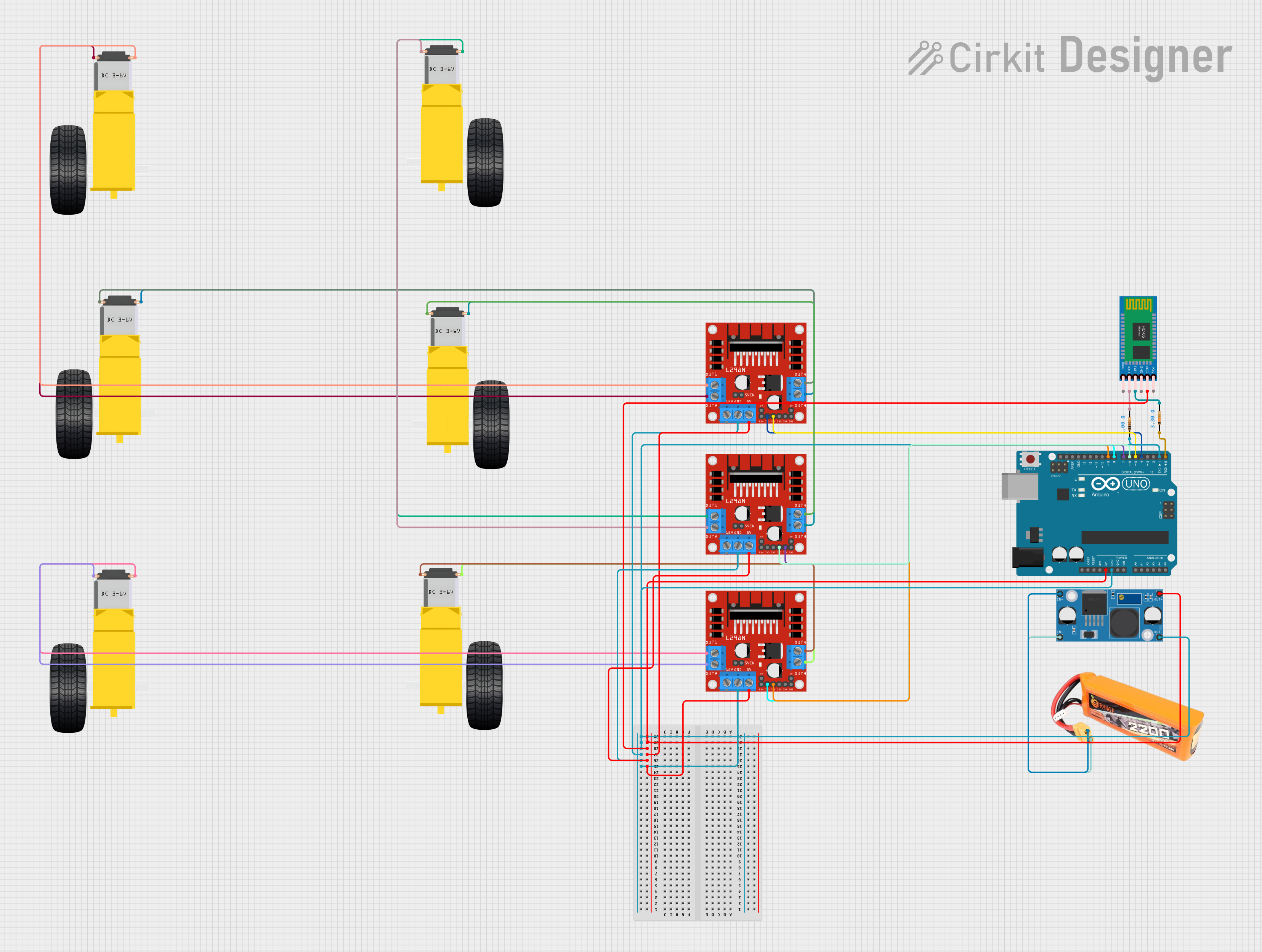
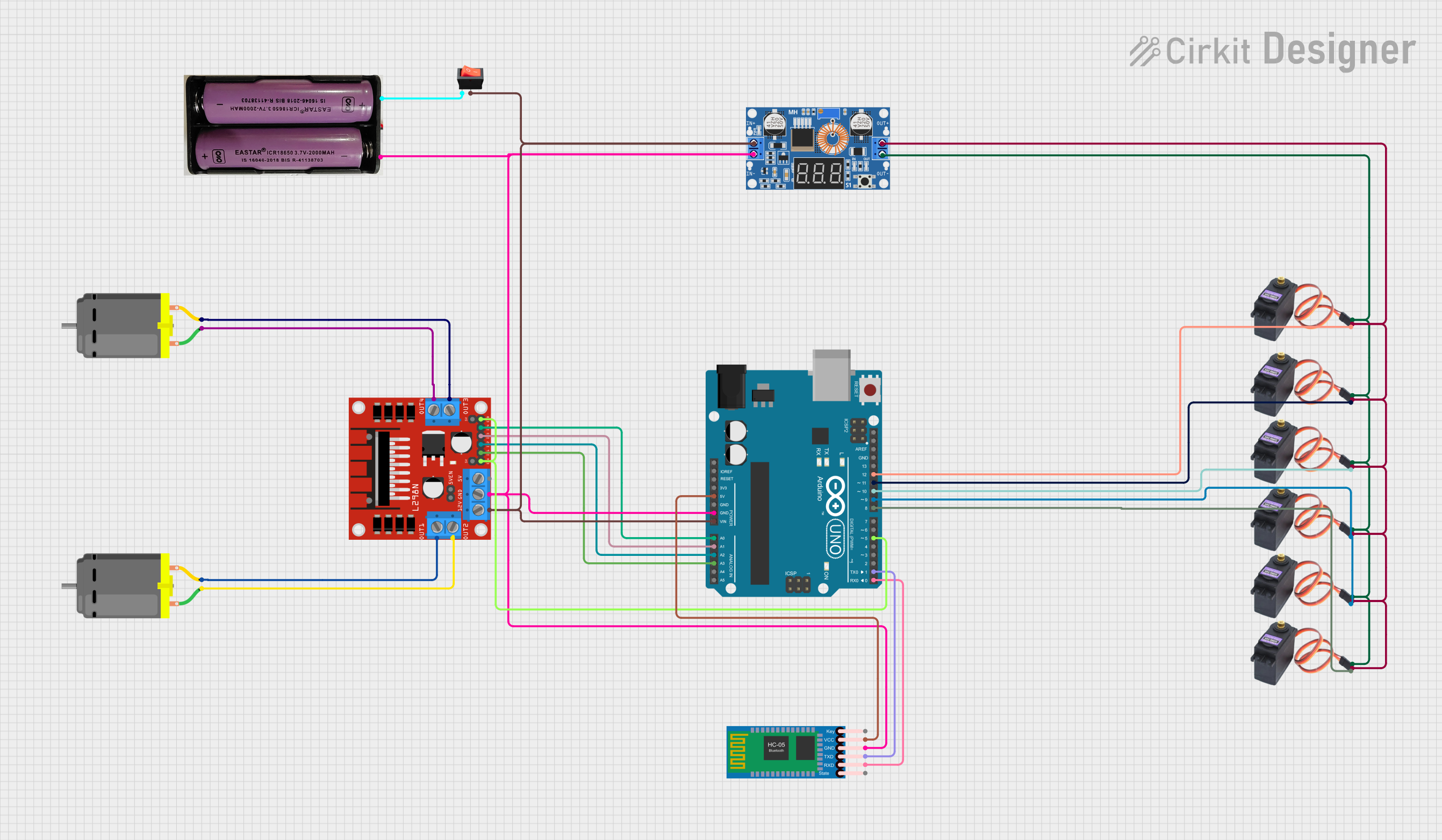
Explore Projects Built with L6470
Common Applications and Use Cases
- CNC machines
- 3D printers
- Automated guided vehicles (AGVs)
- Robotic arms
- Precision dosing pumps
- Office automation machines
Technical Specifications
Key Technical Details
- Operating Voltage: 8 - 45 V
- Maximum Output Current: 3 A
- Microstepping Resolution: up to 1/128 steps
- Programmable speed profile and acceleration/deceleration
- Overcurrent, overtemperature, and undervoltage protection
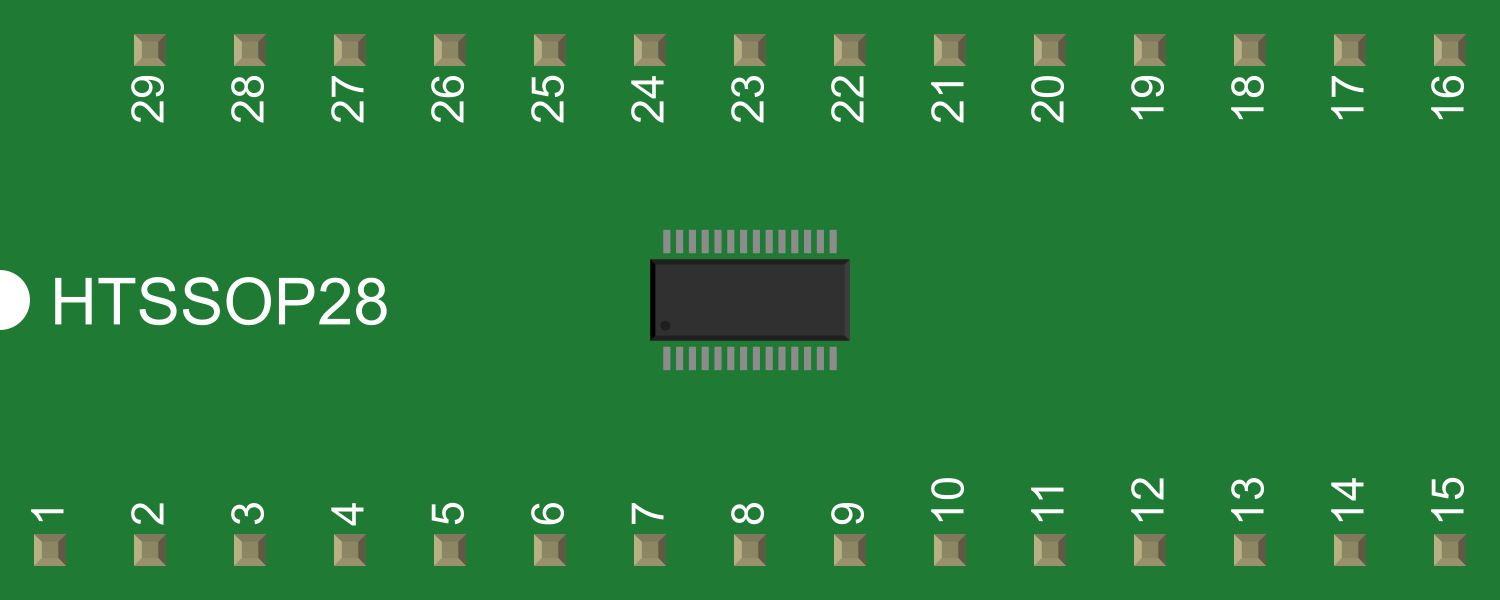
Pin Configuration and Descriptions
| Pin Number | Pin Name | Description |
|---|---|---|
| 1 | VDD | Logic supply voltage (3.3V - 5V) |
| 2 | GND | Ground reference for logic |
| 3 | STCK | Step clock input |
| ... | ... | ... |
| n | BEMF | Back electromotive force output |
Note: This is a simplified representation. Refer to the L6470 datasheet for the complete pinout and descriptions.
Usage Instructions
How to Use the Component in a Circuit
- Power Supply: Connect a suitable power supply to the motor power pins, ensuring it meets the voltage and current requirements.
- Logic Connections: Connect the logic pins (e.g., STCK, DIR) to the microcontroller or control circuitry.
- Motor Connections: Attach the stepper motor leads to the motor output pins, observing the correct coil pairing.
- Configuration: Program the L6470 with the desired motion parameters using SPI communication.
Important Considerations and Best Practices
- Use a decoupling capacitor close to the power pins to minimize voltage spikes.
- Ensure proper heat sinking to deal with power dissipation during operation.
- Configure the overcurrent threshold to prevent damage to the motor or driver.
- Use a pull-up or pull-down resistor on the STCK pin to prevent unintended motor movements.
Example Code for Arduino UNO
#include <SPI.h>

// Define the SPI pins for Arduino UNO
#define CS_PIN 10
#define MOSI_PIN 11
#define MISO_PIN 12
#define SCK_PIN 13

void setup() {
  // Set the SPI pins as outputs
  pinMode(CS_PIN, OUTPUT);
  pinMode(MOSI_PIN, OUTPUT);
  pinMode(MISO_PIN, INPUT);
  pinMode(SCK_PIN, OUTPUT);

  // Initialize SPI communication
  SPI.begin();
  SPI.setDataMode(SPI_MODE3); // L6470 requires SPI Mode 3
}

void loop() {
  // Example: Send a command to move the motor
  digitalWrite(CS_PIN, LOW); // Select the L6470
  SPI.transfer(0x90); // Send move command
  SPI.transfer(0x00); // Send data (number of steps)
  SPI.transfer(0x10); // Send data (number of steps)
  digitalWrite(CS_PIN, HIGH); // Deselect the L6470

  delay(1000); // Wait for a while
}
Note: This is a basic example to demonstrate SPI communication with the L6470. For a complete implementation, refer to the L6470 datasheet and library documentation.
Troubleshooting and FAQs
Common Issues Users Might Face
- Motor not moving: Check power supply, motor connections, and SPI communication.
- Overheating: Ensure proper heat sinking and current settings.
- Unexpected behavior: Verify the configuration parameters and ensure they match the motor specifications.
Solutions and Tips for Troubleshooting
- Power Supply Issues: Use a multimeter to verify the voltage and current supplied to the L6470.
- SPI Communication: Use an oscilloscope to check the SPI signals for correct timing and levels.
- Configuration Parameters: Double-check all programmed settings using the SPI interface.
FAQs
Q: Can the L6470 drive motors at lower voltages? A: The L6470 is designed to operate at a minimum of 8 V. Operating below this voltage may result in reduced performance or failure to function.
Q: How do I set the current limit on the L6470? A: The current limit is set through SPI by programming the appropriate register with the desired current value.
Q: What is the maximum microstepping resolution of the L6470? A: The L6470 supports up to 1/128 microstepping resolution, allowing for smooth and precise motor control.
For more detailed troubleshooting and additional FAQs, refer to the L6470 datasheet and technical support forums.