Cirkit Designer Logo
Cirkit Designer
Your all-in-one circuit design IDE
Home / 
Component Documentation

How to Use 26 by 31 PCB board 2.54mm spacing: Examples, Pinouts, and Specs

Image of 26 by 31 PCB board 2.54mm spacing
Cirkit Designer LogoDesign with 26 by 31 PCB board 2.54mm spacing in Cirkit Designer

Introduction

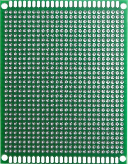
The 26 by 31 PCB board is a compact printed circuit board (PCB) with dimensions of 26mm by 31mm and a standard hole spacing of 2.54mm (0.1 inches). This board is designed for prototyping and assembling electronic circuits, making it an essential tool for hobbyists, students, and professionals alike. Its small size and standardized hole spacing allow for easy mounting of through-hole components and connectors.

Explore Projects Built with 26 by 31 PCB board 2.54mm spacing

Use Cirkit Designer to design, explore, and prototype these projects online. Some projects support real-time simulation. Click "Open Project" to start designing instantly!
RFID-Activated Traffic Light Controller with Auditory Feedback Using Arduino Mega
Image of test: A project utilizing 26 by 31 PCB board 2.54mm spacing in a practical application
This circuit is designed to control two 28BYJ-48 stepper motors using A4988 stepper motor driver carriers, with an Arduino Mega 2560 as the central microcontroller. It includes an RFID-RC522 module for RFID reading, an LCD display for user interface, and a traffic light and piezo speaker for visual and audio signaling. The circuit is powered by a 12V 5A power supply, which is stepped down to 5V for logic level components, and it interfaces with a power outlet for AC to DC conversion.
Cirkit Designer LogoOpen Project in Cirkit Designer
Dual Arduino UNO RFID and Keypad Security System
Image of Projektas: A project utilizing 26 by 31 PCB board 2.54mm spacing in a practical application
This circuit features two Arduino UNO microcontrollers interconnected via their A4 and A5 pins, possibly for I2C communication, and share a common ground. One Arduino is connected to a 4x4 membrane matrix keypad, using digital pins D2 to D9 for keypad interfacing. The other Arduino interfaces with an RFID-RC522 module for RFID reading capabilities and controls three LEDs (red, green, yellow) through digital pins D7 to D9 with 200 Ohm current-limiting resistors.
Cirkit Designer LogoOpen Project in Cirkit Designer
Wi-Fi Controlled Environmental Monitoring System with Dual Stepper Motor Valve Actuation
Image of MVP : A project utilizing 26 by 31 PCB board 2.54mm spacing in a practical application
This circuit features two 28BYJ-48 stepper motors controlled by ULN2003A breakout boards, interfaced with a NodeMCU V3 ESP8266 microcontroller. The NodeMCU collects environmental data from a DHT11 temperature and humidity sensor and an MQ-135 air quality sensor. The microcontroller uses WiFi for connectivity and controls the stepper motors based on the sensor inputs, likely for regulating environmental conditions.
Cirkit Designer LogoOpen Project in Cirkit Designer
Arduino Mega 2560-Controlled Stepper Motors with RFID Access and Traffic Light Indication
Image of Copy of test: A project utilizing 26 by 31 PCB board 2.54mm spacing in a practical application
This circuit controls two 28BYJ-48 stepper motors using A4988 stepper motor driver carriers, interfaced with an Arduino Mega 2560 microcontroller. It features an RFID-RC522 module for RFID reading, a 16x4 LCD display with I2C interface for user interaction, and a piezo speaker for audio feedback. Additionally, there is a traffic light module controlled by the Arduino, and a 48V to 5V converter to step down voltage for the logic levels. The power supply provides 12V to the motor drivers and is connected to a standard power outlet.
Cirkit Designer LogoOpen Project in Cirkit Designer

Explore Projects Built with 26 by 31 PCB board 2.54mm spacing

Use Cirkit Designer to design, explore, and prototype these projects online. Some projects support real-time simulation. Click "Open Project" to start designing instantly!
Image of test: A project utilizing 26 by 31 PCB board 2.54mm spacing in a practical application
RFID-Activated Traffic Light Controller with Auditory Feedback Using Arduino Mega
This circuit is designed to control two 28BYJ-48 stepper motors using A4988 stepper motor driver carriers, with an Arduino Mega 2560 as the central microcontroller. It includes an RFID-RC522 module for RFID reading, an LCD display for user interface, and a traffic light and piezo speaker for visual and audio signaling. The circuit is powered by a 12V 5A power supply, which is stepped down to 5V for logic level components, and it interfaces with a power outlet for AC to DC conversion.
Cirkit Designer LogoOpen Project in Cirkit Designer
Image of Projektas: A project utilizing 26 by 31 PCB board 2.54mm spacing in a practical application
Dual Arduino UNO RFID and Keypad Security System
This circuit features two Arduino UNO microcontrollers interconnected via their A4 and A5 pins, possibly for I2C communication, and share a common ground. One Arduino is connected to a 4x4 membrane matrix keypad, using digital pins D2 to D9 for keypad interfacing. The other Arduino interfaces with an RFID-RC522 module for RFID reading capabilities and controls three LEDs (red, green, yellow) through digital pins D7 to D9 with 200 Ohm current-limiting resistors.
Cirkit Designer LogoOpen Project in Cirkit Designer
Image of MVP : A project utilizing 26 by 31 PCB board 2.54mm spacing in a practical application
Wi-Fi Controlled Environmental Monitoring System with Dual Stepper Motor Valve Actuation
This circuit features two 28BYJ-48 stepper motors controlled by ULN2003A breakout boards, interfaced with a NodeMCU V3 ESP8266 microcontroller. The NodeMCU collects environmental data from a DHT11 temperature and humidity sensor and an MQ-135 air quality sensor. The microcontroller uses WiFi for connectivity and controls the stepper motors based on the sensor inputs, likely for regulating environmental conditions.
Cirkit Designer LogoOpen Project in Cirkit Designer
Image of Copy of test: A project utilizing 26 by 31 PCB board 2.54mm spacing in a practical application
Arduino Mega 2560-Controlled Stepper Motors with RFID Access and Traffic Light Indication
This circuit controls two 28BYJ-48 stepper motors using A4988 stepper motor driver carriers, interfaced with an Arduino Mega 2560 microcontroller. It features an RFID-RC522 module for RFID reading, a 16x4 LCD display with I2C interface for user interaction, and a piezo speaker for audio feedback. Additionally, there is a traffic light module controlled by the Arduino, and a 48V to 5V converter to step down voltage for the logic levels. The power supply provides 12V to the motor drivers and is connected to a standard power outlet.
Cirkit Designer LogoOpen Project in Cirkit Designer

Common Applications and Use Cases

  • Prototyping small electronic circuits
  • Mounting through-hole components such as resistors, capacitors, and ICs
  • Creating custom breakout boards for sensors or modules
  • Educational projects and DIY electronics
  • Repairing or modifying existing circuits

Technical Specifications

Below are the key technical details of the 26 by 31 PCB board:

Specification Details
Dimensions 26mm x 31mm
Hole Spacing 2.54mm (0.1 inches)
Hole Diameter ~1mm (suitable for standard pins)
Material FR4 (fiberglass-reinforced epoxy)
Thickness ~1.6mm
Copper Layer Single-sided or double-sided
Surface Finish HASL (Hot Air Solder Leveling) or ENIG (Electroless Nickel Immersion Gold)
Grid Layout Uniform grid for easy component placement
Compatibility Standard through-hole components

Pin Configuration and Descriptions

The 26 by 31 PCB board does not have predefined pins but features a uniform grid of holes. Each hole can be used to solder components or wires. Below is a description of the layout:

Feature Description
Grid Layout 10 rows x 12 columns of holes
Hole Spacing 2.54mm (standard for DIP components)
Edge Pads May include larger pads for power or ground connections
Mounting Holes May include additional holes for mechanical mounting

Usage Instructions

How to Use the 26 by 31 PCB Board in a Circuit

  1. Plan Your Circuit Layout: Before soldering, sketch the circuit design on paper or use PCB design software to map out component placement.
  2. Insert Components: Place through-hole components (e.g., resistors, capacitors, ICs) into the holes. Ensure proper orientation for polarized components like diodes and electrolytic capacitors.
  3. Solder Connections: Use a soldering iron and solder to secure the components to the board. Trim excess leads with wire cutters.
  4. Create Circuit Traces: Use solder bridges, jumper wires, or thin copper wires to connect the components according to your circuit design.
  5. Test the Circuit: Verify the functionality of your circuit using a multimeter or other testing tools before powering it with a voltage source.

Important Considerations and Best Practices

  • Avoid Overheating: Excessive heat during soldering can damage the PCB or components. Use a temperature-controlled soldering iron.
  • Use Flux: Apply flux to improve solder flow and ensure strong connections.
  • Plan for Power and Ground: Dedicate specific rows or columns for power and ground connections to simplify wiring.
  • Label Connections: Use a marker or labels to identify key connections, especially for complex circuits.
  • Protect the Board: After assembly, consider applying a conformal coating to protect the board from moisture and dust.

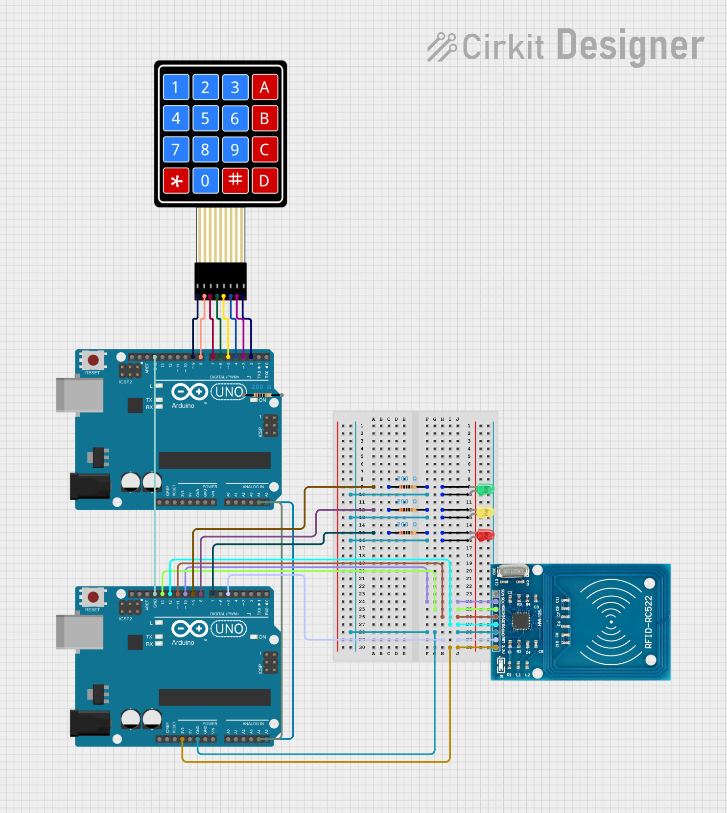
Example: Connecting to an Arduino UNO

The 26 by 31 PCB board can be used to create custom shields or breakout boards for an Arduino UNO. Below is an example of connecting an LED and resistor to an Arduino using the PCB:

Circuit Diagram

  • Connect the LED's anode to a digital pin (e.g., D13) via a 220-ohm resistor.
  • Connect the LED's cathode to the ground (GND).

Arduino Code

// Simple LED Blink Example
// This code blinks an LED connected to pin 13 of the Arduino UNO.

// Define the pin number for the LED
const int ledPin = 13;

void setup() {
  // Set the LED pin as an output
  pinMode(ledPin, OUTPUT);
}

void loop() {
  // Turn the LED on
  digitalWrite(ledPin, HIGH);
  delay(1000); // Wait for 1 second

  // Turn the LED off
  digitalWrite(ledPin, LOW);
  delay(1000); // Wait for 1 second
}

Troubleshooting and FAQs

Common Issues Users Might Face

  1. Cold Solder Joints: Poor solder connections can result in intermittent or failed circuits.
    • Solution: Reheat the joint and apply a small amount of solder to ensure a solid connection.
  2. Short Circuits: Solder bridges between adjacent holes can cause short circuits.
    • Solution: Inspect the board carefully and remove excess solder using a solder wick or desoldering pump.
  3. Component Misplacement: Incorrect placement of polarized components (e.g., diodes, capacitors) can prevent the circuit from functioning.
    • Solution: Double-check the orientation of all components before soldering.
  4. Damaged Traces: Excessive heat or force can damage the copper traces on the PCB.
    • Solution: Use jumper wires to repair broken connections.

FAQs

Q: Can I use this PCB for surface-mount components?
A: While the board is designed for through-hole components, you can use it for surface-mount components by soldering them directly to the copper pads.

Q: What tools do I need to work with this PCB?
A: You will need a soldering iron, solder, wire cutters, flux, and optionally a multimeter for testing.

Q: Is this PCB reusable?
A: Once components are soldered, the board is not easily reusable. However, you can desolder components if needed.

Q: Can I cut the PCB to a smaller size?
A: Yes, the PCB can be cut using a hacksaw or rotary tool, but ensure that the cut does not damage critical traces or components.

This documentation provides a comprehensive guide to using the 26 by 31 PCB board with 2.54mm spacing. Whether you're a beginner or an experienced user, this versatile PCB is an excellent choice for your prototyping needs.