How to Use RTC MODULE: Examples, Pinouts, and Specs
Introduction
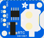
A Real-Time Clock (RTC) module is a device designed to keep track of the current time and date, even when the main power supply is disconnected. It achieves this by using a small backup battery to maintain timekeeping functionality. RTC modules are commonly used in applications where accurate timekeeping is essential, such as data logging, alarms, scheduling, and real-time systems.
Explore Projects Built with RTC MODULE
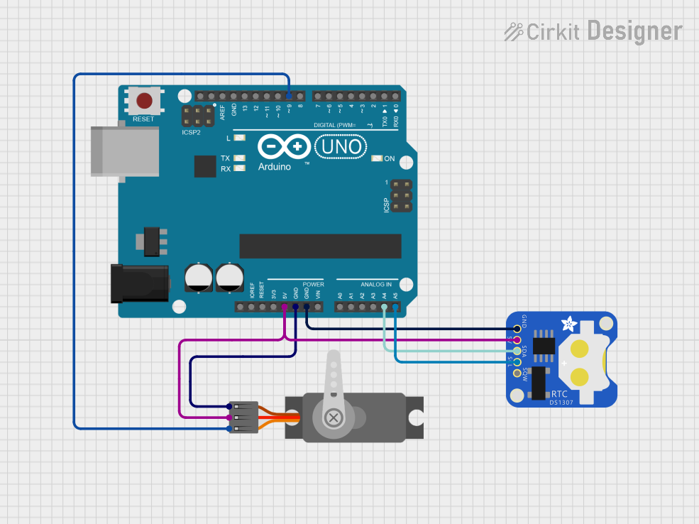
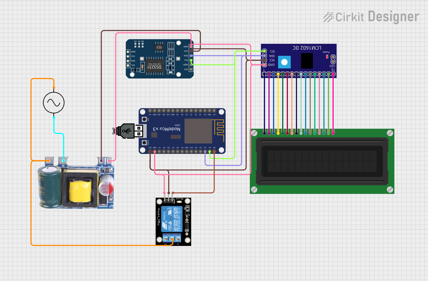


Explore Projects Built with RTC MODULE
Common Applications and Use Cases
- Data Logging: Timestamping sensor data in IoT devices or environmental monitoring systems.
- Alarms and Timers: Triggering events at specific times in automation systems.
- Timekeeping in Embedded Systems: Maintaining accurate time in devices like clocks, thermostats, and smart appliances.
- Power Management: Scheduling power-on/off cycles in energy-efficient systems.
Technical Specifications
Below are the general technical specifications for a typical RTC module, such as the DS3231 or DS1307:
Key Technical Details
- Operating Voltage: 3.3V to 5.5V
- Communication Protocol: I2C (Inter-Integrated Circuit)
- Backup Battery: CR2032 coin cell battery (3V)
- Timekeeping Accuracy: ±2 ppm (DS3231) or ±20 ppm (DS1307)
- Temperature Range: -40°C to +85°C (DS3231) or 0°C to +70°C (DS1307)
- Time Format: 24-hour or 12-hour with AM/PM indication
- Registers: Stores seconds, minutes, hours, day, date, month, and year
- Leap Year Compensation: Automatically adjusts for leap years
Pin Configuration and Descriptions
The following table describes the pinout of a typical RTC module:
| Pin | Name | Description |
|---|---|---|
| 1 | VCC | Power supply input (3.3V or 5V). |
| 2 | GND | Ground connection. |
| 3 | SDA | Serial Data Line for I2C communication. |
| 4 | SCL | Serial Clock Line for I2C communication. |
| 5 | SQW/OUT | Square Wave Output (optional, used for alarms or clock signals). |
| 6 | BAT | Backup battery input (connects to a CR2032 battery to maintain timekeeping). |
Usage Instructions
How to Use the RTC Module in a Circuit
- Power the Module: Connect the VCC pin to a 3.3V or 5V power source and the GND pin to ground.
- Connect to a Microcontroller: Use the SDA and SCL pins to connect the RTC module to the I2C pins of your microcontroller (e.g., Arduino UNO).
- Backup Battery: Insert a CR2032 coin cell battery into the battery holder to ensure timekeeping during power loss.
- Pull-Up Resistors: If not already present on the module, add 4.7kΩ pull-up resistors to the SDA and SCL lines for proper I2C communication.
Important Considerations and Best Practices
- Ensure the backup battery is installed correctly to maintain timekeeping during power outages.
- Use the appropriate library for your microcontroller to simplify communication with the RTC module (e.g.,
RTClibfor Arduino). - Avoid placing the module near high-frequency components to minimize interference.
- Regularly check the battery voltage and replace it when necessary to prevent timekeeping errors.
Example Code for Arduino UNO
Below is an example of how to use the RTC module with an Arduino UNO using the RTClib library:
#include <Wire.h>
#include <RTClib.h>

// Create an RTC object
RTC_DS3231 rtc;

void setup() {
  Serial.begin(9600); // Initialize serial communication at 9600 baud
  Wire.begin();       // Initialize I2C communication

  if (!rtc.begin()) {
    Serial.println("Couldn't find RTC module. Check connections!");
    while (1); // Halt execution if RTC is not found
  }

  if (rtc.lostPower()) {
    Serial.println("RTC lost power, setting the time...");
    // Set the RTC to the current date and time
    rtc.adjust(DateTime(F(__DATE__), F(__TIME__)));
  }
}

void loop() {
  DateTime now = rtc.now(); // Get the current date and time

  // Print the current time to the Serial Monitor
  Serial.print(now.year(), DEC);
  Serial.print('/');
  Serial.print(now.month(), DEC);
  Serial.print('/');
  Serial.print(now.day(), DEC);
  Serial.print(" ");
  Serial.print(now.hour(), DEC);
  Serial.print(':');
  Serial.print(now.minute(), DEC);
  Serial.print(':');
  Serial.print(now.second(), DEC);
  Serial.println();

  delay(1000); // Wait for 1 second before updating
}
Troubleshooting and FAQs
Common Issues and Solutions
RTC Module Not Detected
- Cause: Incorrect wiring or loose connections.
- Solution: Double-check the SDA and SCL connections. Ensure pull-up resistors are in place if required.
Incorrect Time Displayed
- Cause: RTC module lost power or was not initialized properly.
- Solution: Use the
rtc.adjust()function to set the correct time.
Backup Battery Drains Quickly
- Cause: Faulty battery or excessive current draw.
- Solution: Replace the battery and ensure no unnecessary components are connected to the BAT pin.
Interference on I2C Lines
- Cause: High-frequency noise from nearby components.
- Solution: Use shorter wires and keep the RTC module away from noisy components.
FAQs
Q: Can I use the RTC module without a backup battery?
A: Yes, but the time will reset whenever the main power is disconnected.Q: How accurate is the RTC module?
A: The DS3231 is highly accurate (±2 ppm), while the DS1307 is less accurate (±20 ppm).Q: Can I use multiple RTC modules on the same I2C bus?
A: Yes, as long as each module has a unique I2C address. However, most RTC modules have a fixed address, so this may require additional configuration.Q: How do I know if the backup battery is low?
A: Some RTC modules, like the DS3231, have a status register that can indicate low battery voltage.
By following this documentation, you can effectively integrate an RTC module into your projects for reliable timekeeping functionality.