Cirkit Designer Logo
Cirkit Designer
Your all-in-one circuit design IDE
Home / 
Component Documentation

How to Use MAX471: Examples, Pinouts, and Specs

Image of MAX471
Cirkit Designer LogoDesign with MAX471 in Cirkit Designer

Introduction

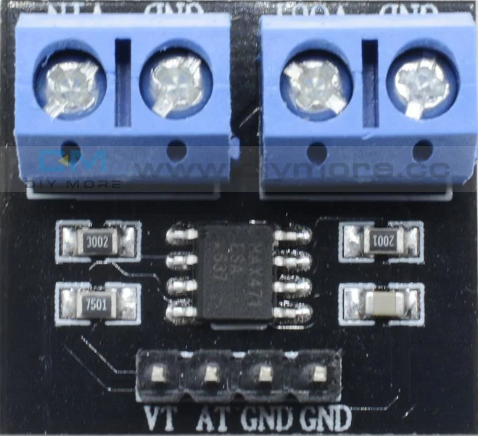
The MAX471 is a high-side current-sense amplifier designed to provide a ground-referenced output voltage proportional to the load current. This component is widely used in current monitoring and battery management applications due to its precision and ease of integration. The MAX471 can measure currents in the range of 0 to 3A, making it suitable for a variety of electronic projects and systems.

Explore Projects Built with MAX471

Use Cirkit Designer to design, explore, and prototype these projects online. Some projects support real-time simulation. Click "Open Project" to start designing instantly!
Sequential Timer-Controlled Relay Switching Circuit
Image of Mark Murry Fantasy Lights: A project utilizing MAX471 in a practical application
This circuit is a sequential relay timer utilizing three 555 timers configured as astable multivibrators to generate timing pulses. These pulses clock a 4017 decade counter, which sequentially activates multiple relay modules. Timing adjustments are possible through potentiometers and fixed resistors, while capacitors set the oscillation frequency.
Cirkit Designer LogoOpen Project in Cirkit Designer
Battery-Powered Emergency Alert System with NUCLEO-F072RB, SIM800L, and GPS NEO 6M
Image of women safety: A project utilizing MAX471 in a practical application
This circuit is an emergency alert system that uses a NUCLEO-F072RB microcontroller to send SMS alerts and make calls via a SIM800L GSM module, while obtaining location data from a GPS NEO 6M module. The system is powered by a Li-ion battery and includes a TP4056 module for battery charging and protection, with a rocker switch to control power to the microcontroller.
Cirkit Designer LogoOpen Project in Cirkit Designer
Arduino UNO Based Automated Pill Dispenser with GSM Notifications and RTC Scheduling
Image of MEDICAL DISPENSER: A project utilizing MAX471 in a practical application
This circuit is designed as an automated pill dispenser with scheduled alerts and manual pill-taking confirmation. It uses an Arduino UNO to control three servos for dispensing pills at predefined times, indicated by an I2C LCD screen and a DS3231 RTC for timekeeping. The system can send SMS notifications via the Sim800l GSM module and provides reminders with a piezo buzzer, while user interactions are handled through pushbuttons.
Cirkit Designer LogoOpen Project in Cirkit Designer
Teensy 4.1-Based Multi-Channel Potentiometer Interface with 74HC4051 Mux and AMS1117 3.3V Regulator
Image of redrum: A project utilizing MAX471 in a practical application
This circuit features a Teensy 4.1 microcontroller interfaced with a SparkFun 74HC4051 8-channel multiplexer to read multiple rotary potentiometers. The AMS1117 3.3V voltage regulator provides a stable 3.3V supply to the multiplexer and potentiometers, while electrolytic and ceramic capacitors are used for power supply filtering and stabilization.
Cirkit Designer LogoOpen Project in Cirkit Designer

Explore Projects Built with MAX471

Use Cirkit Designer to design, explore, and prototype these projects online. Some projects support real-time simulation. Click "Open Project" to start designing instantly!
Image of Mark Murry Fantasy Lights: A project utilizing MAX471 in a practical application
Sequential Timer-Controlled Relay Switching Circuit
This circuit is a sequential relay timer utilizing three 555 timers configured as astable multivibrators to generate timing pulses. These pulses clock a 4017 decade counter, which sequentially activates multiple relay modules. Timing adjustments are possible through potentiometers and fixed resistors, while capacitors set the oscillation frequency.
Cirkit Designer LogoOpen Project in Cirkit Designer
Image of women safety: A project utilizing MAX471 in a practical application
Battery-Powered Emergency Alert System with NUCLEO-F072RB, SIM800L, and GPS NEO 6M
This circuit is an emergency alert system that uses a NUCLEO-F072RB microcontroller to send SMS alerts and make calls via a SIM800L GSM module, while obtaining location data from a GPS NEO 6M module. The system is powered by a Li-ion battery and includes a TP4056 module for battery charging and protection, with a rocker switch to control power to the microcontroller.
Cirkit Designer LogoOpen Project in Cirkit Designer
Image of MEDICAL DISPENSER: A project utilizing MAX471 in a practical application
Arduino UNO Based Automated Pill Dispenser with GSM Notifications and RTC Scheduling
This circuit is designed as an automated pill dispenser with scheduled alerts and manual pill-taking confirmation. It uses an Arduino UNO to control three servos for dispensing pills at predefined times, indicated by an I2C LCD screen and a DS3231 RTC for timekeeping. The system can send SMS notifications via the Sim800l GSM module and provides reminders with a piezo buzzer, while user interactions are handled through pushbuttons.
Cirkit Designer LogoOpen Project in Cirkit Designer
Image of redrum: A project utilizing MAX471 in a practical application
Teensy 4.1-Based Multi-Channel Potentiometer Interface with 74HC4051 Mux and AMS1117 3.3V Regulator
This circuit features a Teensy 4.1 microcontroller interfaced with a SparkFun 74HC4051 8-channel multiplexer to read multiple rotary potentiometers. The AMS1117 3.3V voltage regulator provides a stable 3.3V supply to the multiplexer and potentiometers, while electrolytic and ceramic capacitors are used for power supply filtering and stabilization.
Cirkit Designer LogoOpen Project in Cirkit Designer

Technical Specifications

Key Technical Details

Parameter Value
Supply Voltage 3V to 36V
Output Voltage Range 0V to 5V
Current Range 0A to 3A
Gain 1V/A
Operating Temperature -40°C to +85°C
Package 8-Pin SOIC

Pin Configuration and Descriptions

Pin Number Pin Name Description
1 V+ Positive supply voltage (3V to 36V)
2 OUT Output voltage proportional to the load current
3 GND Ground
4 RS+ Positive input for current sense resistor
5 RS- Negative input for current sense resistor
6 NC No connection
7 NC No connection
8 V- Negative supply voltage (typically ground)

Usage Instructions

How to Use the MAX471 in a Circuit

  1. Power Supply: Connect the V+ pin to a positive supply voltage (3V to 36V) and the V- pin to ground.
  2. Current Sensing: Connect the RS+ and RS- pins across a current sense resistor placed in the high-side of the load circuit.
  3. Output: The OUT pin provides a voltage proportional to the load current. This output can be read by an ADC (Analog-to-Digital Converter) or a microcontroller.

Important Considerations and Best Practices

  • Current Sense Resistor: Choose a low-value, high-precision resistor to minimize power loss and ensure accurate current measurement.
  • Filtering: Add a capacitor between the OUT pin and ground to filter out noise and stabilize the output voltage.
  • Thermal Management: Ensure proper thermal management, especially in high-current applications, to prevent overheating.
  • PCB Layout: Keep the traces between the current sense resistor and the MAX471 as short as possible to reduce noise and resistance.

Example Circuit with Arduino UNO

/*
  Example code to read current using MAX471 with Arduino UNO.
  Connect the OUT pin of MAX471 to A0 pin of Arduino.
*/

const int analogPin = A0; // Analog pin connected to OUT pin of MAX471
float voltage = 0;        // Variable to store the voltage reading
float current = 0;        // Variable to store the calculated current

void setup() {
  Serial.begin(9600); // Initialize serial communication
}

void loop() {
  voltage = analogRead(analogPin) * (5.0 / 1023.0); // Read and convert voltage
  current = voltage; // Since gain is 1V/A, voltage directly gives current in A

  Serial.print("Current: ");
  Serial.print(current);
  Serial.println(" A");

  delay(1000); // Wait for 1 second before next reading
}

Troubleshooting and FAQs

Common Issues and Solutions

  1. No Output Voltage:

    • Check Connections: Ensure all connections are secure and correct.
    • Power Supply: Verify that the supply voltage is within the specified range.
  2. Inaccurate Current Measurement:

    • Sense Resistor: Ensure the current sense resistor is of the correct value and precision.
    • Noise: Add a capacitor between the OUT pin and ground to filter out noise.
  3. Overheating:

    • Current Rating: Ensure the current through the MAX471 does not exceed its maximum rating.
    • Thermal Management: Improve cooling or reduce the load current.

FAQs

Q1: Can the MAX471 measure negative currents?

  • No, the MAX471 is designed to measure positive currents only.

Q2: What is the maximum current the MAX471 can measure?

  • The MAX471 can measure currents up to 3A.

Q3: Can I use the MAX471 with a 5V supply?

  • Yes, the MAX471 can operate with a supply voltage as low as 3V and as high as 36V.

Q4: How do I improve the accuracy of current measurements?

  • Use a high-precision, low-value current sense resistor and add a filtering capacitor to the output.

By following this documentation, users can effectively integrate the MAX471 into their projects for accurate current sensing and monitoring.