How to Use CC1101: Examples, Pinouts, and Specs
Introduction
The CC1101 is a low-power sub-1 GHz transceiver designed for wireless communication in the ISM (Industrial, Scientific, and Medical) and SRD (Short Range Device) frequency bands. Manufactured by Fart, this versatile component supports multiple modulation formats, including ASK, FSK, GFSK, and MSK, making it suitable for a wide range of applications. Its low power consumption and robust performance make it ideal for battery-powered devices.
Explore Projects Built with CC1101


Explore Projects Built with CC1101
Common Applications
- Remote control systems (e.g., garage doors, drones)
- Wireless sensor networks
- Home automation systems
- Industrial monitoring and control
- Smart metering and telemetry
Technical Specifications
The CC1101 is a highly configurable transceiver with the following key specifications:
| Parameter | Value |
|---|---|
| Frequency Range | 300 MHz to 928 MHz (programmable) |
| Modulation Formats | ASK, FSK, GFSK, MSK |
| Data Rate | 0.6 kbps to 600 kbps |
| Supply Voltage | 1.8 V to 3.6 V |
| Current Consumption | 14.7 mA (RX mode), 12.7 mA (TX mode at 10 dBm output power) |
| Output Power | Programmable from -30 dBm to +12 dBm |
| Sensitivity | -116 dBm at 1.2 kbps (2-FSK, 868 MHz) |
| Operating Temperature | -40°C to +85°C |
| Interface | SPI (Serial Peripheral Interface) |
Pin Configuration and Descriptions
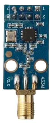
The CC1101 comes in a 20-pin QFN package. Below is the pin configuration:
| Pin Number | Pin Name | Description |
|---|---|---|
| 1 | GND | Ground connection |
| 2 | GDO2 | General-purpose digital output pin 2 |
| 3 | GDO0 | General-purpose digital output pin 0 |
| 4 | GDO1 | General-purpose digital output pin 1 |
| 5 | VDD | Power supply input (1.8 V to 3.6 V) |
| 6 | SI | SPI data input |
| 7 | SO | SPI data output |
| 8 | SCLK | SPI clock input |
| 9 | CSn | SPI chip select (active low) |
| 10 | GND | Ground connection |
| 11-20 | RF_P, RF_N | Differential RF input/output for antenna connection |
Usage Instructions
How to Use the CC1101 in a Circuit
- Power Supply: Connect the VDD pin to a regulated power supply (1.8 V to 3.6 V) and ensure proper decoupling capacitors are placed close to the pin.
- SPI Interface: Connect the SPI pins (SI, SO, SCLK, CSn) to a microcontroller or processor for communication. Ensure the SPI clock speed does not exceed 10 MHz.
- Antenna Connection: Use the RF_P and RF_N pins to connect a suitable antenna. A matching network may be required for optimal performance.
- GPIO Configuration: Configure the GDO pins for specific functions such as interrupts, data output, or status signals.
- Programming: Use the SPI interface to configure the CC1101 registers for the desired frequency, modulation, and data rate.
Important Considerations
- Crystal Oscillator: The CC1101 requires an external 26 MHz crystal oscillator for proper operation.
- Impedance Matching: Ensure proper impedance matching for the RF section to maximize range and efficiency.
- Regulatory Compliance: Verify that your design complies with local regulations for the frequency band and output power.
Example: Connecting CC1101 to Arduino UNO
Below is an example of how to connect the CC1101 to an Arduino UNO and send data:
Wiring Diagram
| CC1101 Pin | Arduino UNO Pin |
|---|---|
| VDD | 3.3V |
| GND | GND |
| SI | Pin 11 (MOSI) |
| SO | Pin 12 (MISO) |
| SCLK | Pin 13 (SCK) |
| CSn | Pin 10 |
| GDO0 | Pin 2 (Interrupt) |
Arduino Code
#include <SPI.h>

// Define CC1101 pins
#define CSn 10
#define GDO0 2

void setup() {
  // Initialize SPI
  SPI.begin();
  pinMode(CSn, OUTPUT);
  pinMode(GDO0, INPUT);
  digitalWrite(CSn, HIGH); // Set CSn high to deselect CC1101

  Serial.begin(9600);
  Serial.println("Initializing CC1101...");

  // Example: Reset CC1101
  resetCC1101();
}

void loop() {
  // Example: Transmit data
  sendData("Hello, CC1101!");
  delay(1000);
}

void resetCC1101() {
  digitalWrite(CSn, LOW); // Select CC1101
  delay(1);
  digitalWrite(CSn, HIGH); // Deselect CC1101
  delay(1);
  digitalWrite(CSn, LOW); // Select CC1101 again
  delay(1);
  digitalWrite(CSn, HIGH); // Deselect CC1101
  delay(1);
  Serial.println("CC1101 reset complete.");
}

void sendData(const char *data) {
  digitalWrite(CSn, LOW); // Select CC1101
  SPI.transfer(0x3F); // Example: Write command
  for (int i = 0; data[i] != '\0'; i++) {
    SPI.transfer(data[i]); // Send data byte by byte
  }
  digitalWrite(CSn, HIGH); // Deselect CC1101
  Serial.println("Data sent: " + String(data));
}
Troubleshooting and FAQs
Common Issues
No Communication with CC1101
- Ensure the SPI connections are correct and the clock speed is within the specified range.
- Verify that the CSn pin is properly toggled during communication.
Low RF Range
- Check the antenna design and ensure proper impedance matching.
- Verify that the output power is configured correctly in the CC1101 registers.
High Power Consumption
- Ensure the CC1101 is in the correct power-saving mode when not transmitting or receiving.
- Check for any unintentional high-frequency noise on the power supply.
FAQs
Q: Can the CC1101 operate at 2.4 GHz?
A: No, the CC1101 is designed for sub-1 GHz frequencies (300 MHz to 928 MHz).
Q: What is the maximum data rate supported by the CC1101?
A: The CC1101 supports data rates up to 600 kbps.
Q: How do I configure the CC1101 for a specific frequency?
A: Use the SPI interface to write the desired frequency settings to the frequency control registers (FREQ2, FREQ1, FREQ0).
Q: Can I use the CC1101 with a 5V microcontroller?
A: Yes, but you must use level shifters or voltage dividers to ensure the SPI signals are within the CC1101's voltage range (1.8 V to 3.6 V).