
How to Use Servo MG90S: Examples, Pinouts, and Specs
 Design with Servo MG90S in Cirkit Designer
Introduction
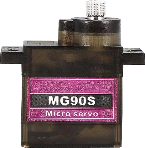
The MG90S is a small, lightweight servo motor widely used in robotics, RC vehicles, and hobby projects. It features a durable metal gear system, ensuring improved precision and longevity compared to plastic gear servos. The MG90S operates within a voltage range of 4.8V to 6.0V and provides a rotation angle of approximately 180 degrees. Its compact size and reliable performance make it an excellent choice for applications where space is limited and precise control is required.
Explore Projects Built with Servo MG90S
 Open Project in Cirkit Designer
 Open Project in Cirkit Designer
 Open Project in Cirkit Designer
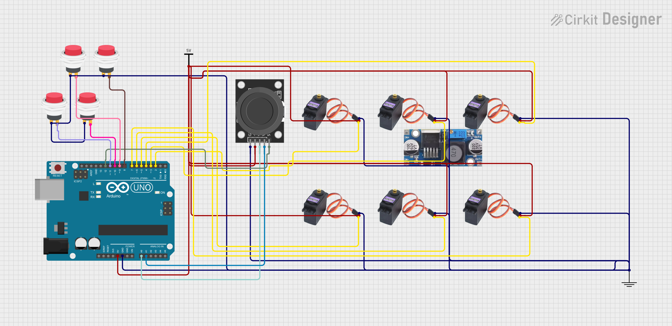 Open Project in Cirkit Designer
Explore Projects Built with Servo MG90S
Open Project in Cirkit DesignerOpen Project in Cirkit DesignerOpen Project in Cirkit DesignerOpen Project in Cirkit DesignerCommon Applications
- Robotic arms and grippers
- RC vehicles (cars, boats, planes)
- Pan-tilt camera systems
- Automated mechanisms in hobby projects
- Educational electronics and prototyping
Technical Specifications
Below are the key technical details of the MG90S servo motor:
| Parameter | Specification |
|---|---|
| Operating Voltage | 4.8V to 6.0V |
| Stall Torque | 1.8 kg·cm (4.8V), 2.2 kg·cm (6.0V) |
| Operating Speed | 0.1 s/60° (4.8V), 0.08 s/60° (6.0V) |
| Rotation Angle | ~180° |
| Gear Type | Metal |
| Weight | 13.4 g |
| Dimensions | 22.8 x 12.2 x 28.5 mm |
| Connector Type | 3-pin female header |
Pin Configuration
The MG90S servo motor has a 3-pin connector with the following pinout:
| Pin Number | Wire Color | Function |
|---|---|---|
| 1 | Brown | Ground (GND) |
| 2 | Red | Power (VCC) |
| 3 | Orange | Signal (PWM input) |
Usage Instructions
Connecting the MG90S to a Circuit
- Power Supply: Connect the red wire to a 5V power source (or 6V for higher torque). Ensure the power supply can provide sufficient current (at least 1A is recommended).
- Ground: Connect the brown wire to the ground (GND) of your circuit.
- Signal: Connect the orange wire to a PWM-capable pin on your microcontroller (e.g., Arduino).
Important Considerations
- Voltage Range: Do not exceed the 6.0V maximum operating voltage to avoid damaging the servo.
- Current Requirements: Ensure your power supply can handle the current draw, especially under load.
- PWM Signal: The MG90S requires a PWM signal with a pulse width between 1 ms (0°) and 2 ms (180°). A 1.5 ms pulse corresponds to the neutral position (90°).
- Mechanical Limits: Avoid forcing the servo beyond its physical rotation limits to prevent damage.
Example: Using the MG90S with Arduino UNO
Below is an example code to control the MG90S servo motor using an Arduino UNO:
#include <Servo.h> // Include the Servo library

Servo myServo; // Create a Servo object to control the MG90S

void setup() {
  myServo.attach(9); // Attach the servo to pin 9 on the Arduino
}

void loop() {
  myServo.write(0); // Move the servo to 0 degrees
  delay(1000); // Wait for 1 second

  myServo.write(90); // Move the servo to 90 degrees
  delay(1000); // Wait for 1 second

  myServo.write(180); // Move the servo to 180 degrees
  delay(1000); // Wait for 1 second
}
Best Practices
- Use a dedicated power supply for the servo if your circuit includes multiple components to avoid voltage drops.
- Secure the servo firmly in place to prevent vibrations or misalignment during operation.
- Calibrate the servo's range of motion in your code to ensure it operates within safe limits.
Troubleshooting and FAQs
Common Issues
Servo Not Moving
- Cause: Incorrect wiring or insufficient power supply.
- Solution: Double-check the connections and ensure the power supply meets the servo's voltage and current requirements.
Servo Jittering
- Cause: Electrical noise or unstable power supply.
- Solution: Use a capacitor (e.g., 100 µF) across the power and ground lines to stabilize the voltage.
Servo Overheating
- Cause: Prolonged operation under heavy load or exceeding voltage limits.
- Solution: Reduce the load on the servo or ensure the operating voltage is within the specified range.
Limited Rotation
- Cause: Incorrect PWM signal or mechanical obstruction.
- Solution: Verify the PWM signal timing and ensure there are no physical obstructions.
FAQs
Q: Can the MG90S rotate continuously?
A: No, the MG90S is a standard servo with a rotation range of approximately 180°. For continuous rotation, use a continuous rotation servo.
Q: Can I power the MG90S directly from the Arduino?
A: While possible, it is not recommended as the Arduino's 5V pin may not provide sufficient current under load. Use an external power supply for reliable operation.
Q: How do I know if the servo is receiving a signal?
A: The servo will typically make a slight noise or move to its default position when powered and receiving a valid PWM signal.
Q: Can I use the MG90S with a Raspberry Pi?
A: Yes, but you will need to generate a PWM signal using a library like RPi.GPIO or an external PWM controller for precise control.