Cirkit Designer Logo
Cirkit Designer
Your all-in-one circuit design IDE
Home / 
Component Documentation

How to Use Automatic Power Switch Module, 12V Battery Charger, 12V Battery Charger Module: Examples, Pinouts, and Specs

Image of Automatic Power Switch Module, 12V Battery Charger, 12V Battery Charger Module
Cirkit Designer LogoDesign with Automatic Power Switch Module, 12V Battery Charger, 12V Battery Charger Module in Cirkit Designer

Introduction

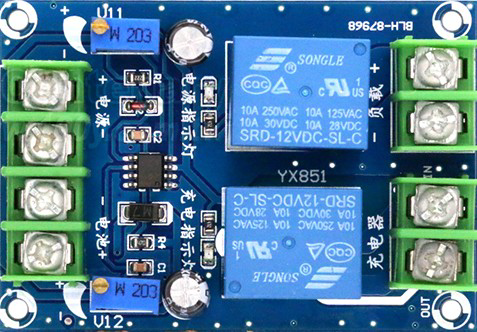
The Automatic Power Switch Module, 12V Battery Charger Module, is a versatile electronic component designed to manage the charging of 12V lead-acid or lithium batteries. It automatically switches between power sources, ensuring uninterrupted power delivery to connected devices while protecting the battery from overcharging or deep discharge. This module is ideal for applications requiring reliable power management, such as solar power systems, backup power supplies, and automotive electronics.

Explore Projects Built with Automatic Power Switch Module, 12V Battery Charger, 12V Battery Charger Module

Use Cirkit Designer to design, explore, and prototype these projects online. Some projects support real-time simulation. Click "Open Project" to start designing instantly!
12V Power Supply with HX-M350 Backup Battery Switching
Image of power : A project utilizing Automatic Power Switch Module, 12V Battery Charger, 12V Battery Charger Module in a practical application
This circuit is designed to provide a backup power solution using a 12V 200Ah battery and a 12V power supply, with the HX-M350 module managing the switching between these power sources. The HX-M350 module automatically switches to the battery power when the main 12V power supply fails or is unavailable, ensuring uninterrupted power to the load. There is no microcontroller or additional control logic involved, indicating that the switching mechanism is likely handled entirely by the HX-M350 module itself.
Cirkit Designer LogoOpen Project in Cirkit Designer
12V UPS System with Dual 18650 Li-ion Battery Backup and Voltage Regulation
Image of Power supply: A project utilizing Automatic Power Switch Module, 12V Battery Charger, 12V Battery Charger Module in a practical application
This circuit is designed to provide an uninterruptible power supply (UPS) system with a 12V DC output. It includes a 12V 5A power supply connected to an AC source through a toggle switch, which charges a pair of 18650 Li-ion batteries via a voltage regulator (XL4016). The UPS module ensures a continuous power supply to the load by switching between the power supply and the battery bank.
Cirkit Designer LogoOpen Project in Cirkit Designer
Solar-Powered Battery Backup System with Automatic Transfer Switch
Image of POWER SUPPLY: A project utilizing Automatic Power Switch Module, 12V Battery Charger, 12V Battery Charger Module in a practical application
This circuit is a solar power management system that integrates a solar panel, battery, and inverter to provide a stable 12V DC and 220V AC output. It includes automatic transfer switches (ATS) and circuit breakers for safety and reliability, as well as a low voltage disconnect to protect the battery from deep discharge.
Cirkit Designer LogoOpen Project in Cirkit Designer
Solar-Powered Dual Source Automatic Transfer Switch System
Image of Ats SCHEMATIC: A project utilizing Automatic Power Switch Module, 12V Battery Charger, 12V Battery Charger Module in a practical application
This circuit is designed to manage power from two sources: a solar panel and a 12V battery, with a dual power automatic transfer switch to select between them. The solar panel and battery are connected to a charge controller, which regulates the charging process and provides power to a load through a power inverter. Safety is ensured with the use of fuses and circuit breakers, and the power inverter converts DC to AC for use with standard 220V appliances.
Cirkit Designer LogoOpen Project in Cirkit Designer

Explore Projects Built with Automatic Power Switch Module, 12V Battery Charger, 12V Battery Charger Module

Use Cirkit Designer to design, explore, and prototype these projects online. Some projects support real-time simulation. Click "Open Project" to start designing instantly!
Image of power : A project utilizing Automatic Power Switch Module, 12V Battery Charger, 12V Battery Charger Module in a practical application
12V Power Supply with HX-M350 Backup Battery Switching
This circuit is designed to provide a backup power solution using a 12V 200Ah battery and a 12V power supply, with the HX-M350 module managing the switching between these power sources. The HX-M350 module automatically switches to the battery power when the main 12V power supply fails or is unavailable, ensuring uninterrupted power to the load. There is no microcontroller or additional control logic involved, indicating that the switching mechanism is likely handled entirely by the HX-M350 module itself.
Cirkit Designer LogoOpen Project in Cirkit Designer
Image of Power supply: A project utilizing Automatic Power Switch Module, 12V Battery Charger, 12V Battery Charger Module in a practical application
12V UPS System with Dual 18650 Li-ion Battery Backup and Voltage Regulation
This circuit is designed to provide an uninterruptible power supply (UPS) system with a 12V DC output. It includes a 12V 5A power supply connected to an AC source through a toggle switch, which charges a pair of 18650 Li-ion batteries via a voltage regulator (XL4016). The UPS module ensures a continuous power supply to the load by switching between the power supply and the battery bank.
Cirkit Designer LogoOpen Project in Cirkit Designer
Image of POWER SUPPLY: A project utilizing Automatic Power Switch Module, 12V Battery Charger, 12V Battery Charger Module in a practical application
Solar-Powered Battery Backup System with Automatic Transfer Switch
This circuit is a solar power management system that integrates a solar panel, battery, and inverter to provide a stable 12V DC and 220V AC output. It includes automatic transfer switches (ATS) and circuit breakers for safety and reliability, as well as a low voltage disconnect to protect the battery from deep discharge.
Cirkit Designer LogoOpen Project in Cirkit Designer
Image of Ats SCHEMATIC: A project utilizing Automatic Power Switch Module, 12V Battery Charger, 12V Battery Charger Module in a practical application
Solar-Powered Dual Source Automatic Transfer Switch System
This circuit is designed to manage power from two sources: a solar panel and a 12V battery, with a dual power automatic transfer switch to select between them. The solar panel and battery are connected to a charge controller, which regulates the charging process and provides power to a load through a power inverter. Safety is ensured with the use of fuses and circuit breakers, and the power inverter converts DC to AC for use with standard 220V appliances.
Cirkit Designer LogoOpen Project in Cirkit Designer

Common Applications:

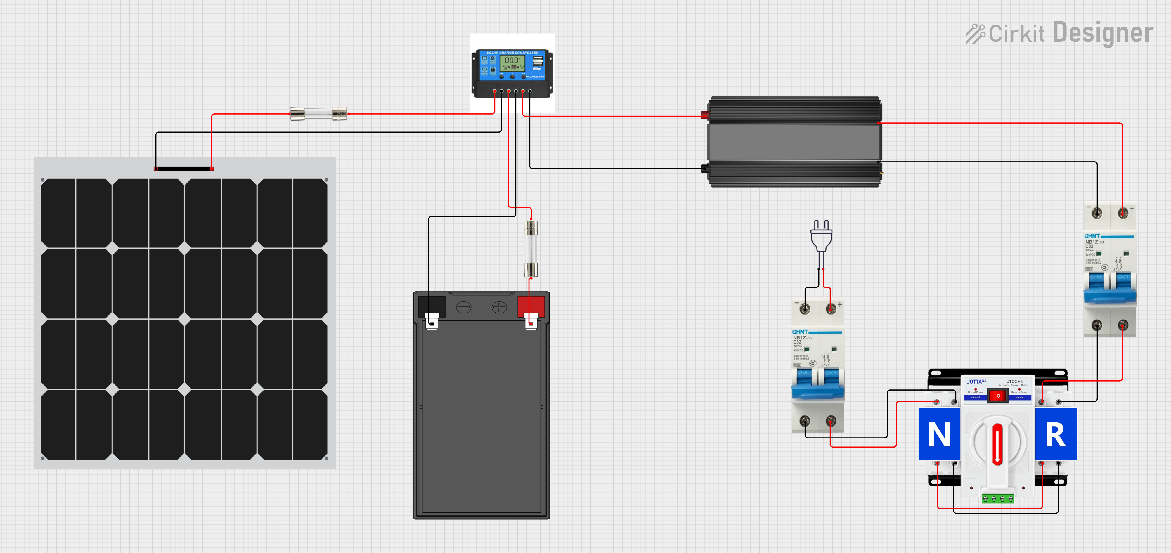
  • Solar power systems for charging 12V batteries
  • Uninterruptible power supplies (UPS)
  • Automotive battery management
  • Emergency lighting systems
  • DIY electronics projects requiring battery backup

Technical Specifications

Below are the key technical details and pin configurations for the module:

Key Technical Details:

Parameter Value
Input Voltage Range 12V DC (nominal)
Output Voltage 12V DC (regulated)
Maximum Input Current 10A
Battery Type Supported Lead-acid, Lithium-ion (12V)
Charging Current Up to 10A (depending on input)
Overcharge Protection Yes
Deep Discharge Protection Yes
Operating Temperature -20°C to 60°C
Dimensions 60mm x 40mm x 20mm

Pin Configuration and Descriptions:

Pin Name Description
VIN+ Positive terminal for the input power supply (e.g., solar panel or adapter)
VIN- Negative terminal for the input power supply
BAT+ Positive terminal for the battery connection
BAT- Negative terminal for the battery connection
LOAD+ Positive terminal for the load (connected device)
LOAD- Negative terminal for the load

Usage Instructions

How to Use the Module in a Circuit:

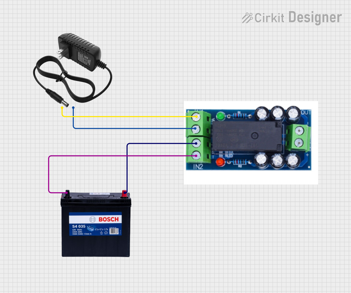
  1. Connect the Input Power Source:

    • Attach the positive terminal of your power source (e.g., solar panel or DC adapter) to the VIN+ pin.
    • Connect the negative terminal of the power source to the VIN- pin.
  2. Connect the Battery:

    • Attach the positive terminal of the 12V battery to the BAT+ pin.
    • Connect the negative terminal of the battery to the BAT- pin.
  3. Connect the Load:

    • Attach the positive terminal of the load (e.g., a 12V device) to the LOAD+ pin.
    • Connect the negative terminal of the load to the LOAD- pin.
  4. Power On:

    • Once all connections are secure, power on the input source. The module will automatically manage the charging of the battery and supply power to the load.

Important Considerations and Best Practices:

  • Ensure the input voltage is within the specified range (12V DC nominal).
  • Use appropriate wire gauges to handle the current (e.g., 16 AWG or thicker for high currents).
  • Avoid short circuits between pins to prevent damage to the module.
  • Place the module in a well-ventilated area to prevent overheating.
  • If using a lithium battery, ensure it has a built-in Battery Management System (BMS) for additional safety.

Example Arduino UNO Integration:

While this module does not directly interface with an Arduino, you can monitor the battery voltage using an Arduino UNO. Below is an example code snippet to read the battery voltage:

// Define the analog pin connected to the battery voltage divider
const int batteryPin = A0;

// Voltage divider resistor values (in ohms)
const float R1 = 10000.0; // Resistor connected to BAT+
const float R2 = 1000.0;  // Resistor connected to GND

void setup() {
  Serial.begin(9600); // Initialize serial communication
}

void loop() {
  int analogValue = analogRead(batteryPin); // Read analog value
  float voltage = (analogValue / 1023.0) * 5.0; // Convert to voltage (Arduino 5V ADC)
  voltage = voltage * ((R1 + R2) / R2); // Adjust for voltage divider ratio

  Serial.print("Battery Voltage: ");
  Serial.print(voltage);
  Serial.println(" V");

  delay(1000); // Wait 1 second before next reading
}

Note: Use a voltage divider to scale down the battery voltage to within the Arduino's 5V ADC range. Adjust R1 and R2 values as needed.

Troubleshooting and FAQs

Common Issues and Solutions:

  1. Module Not Charging the Battery:

    • Cause: Input voltage is too low or disconnected.
    • Solution: Verify the input voltage is within the specified range (12V DC nominal).
  2. Load Not Receiving Power:

    • Cause: Loose connections or battery is deeply discharged.
    • Solution: Check all connections and ensure the battery is not below its minimum voltage.
  3. Overheating:

    • Cause: Excessive current draw or poor ventilation.
    • Solution: Reduce the load current or improve ventilation around the module.
  4. Battery Overcharging:

    • Cause: Faulty overcharge protection or incorrect battery type.
    • Solution: Ensure the battery type is supported and has a built-in BMS if lithium-based.

FAQs:

  • Can this module charge other battery types?

    • No, it is designed specifically for 12V lead-acid and lithium batteries.
  • What happens if the input power source is disconnected?

    • The module will automatically switch to battery power to supply the load.
  • Can I use this module with a solar panel?

    • Yes, it is compatible with solar panels as long as the output voltage is within the specified range.
  • Is additional cooling required?

    • Not typically, but ensure proper ventilation if operating at high currents for extended periods.

This documentation provides a comprehensive guide to using the Automatic Power Switch Module, 12V Battery Charger Module effectively and safely.