How to Use ldome6211: Examples, Pinouts, and Specs
Introduction
The LDOME6211 is a high-performance LED driver designed to drive multiple LEDs in either series or parallel configurations. It features an adjustable current output, making it suitable for a wide range of LED applications. Additionally, the LDOME6211 includes built-in thermal protection to ensure safe and reliable operation under varying environmental conditions.
Explore Projects Built with ldome6211


Explore Projects Built with ldome6211
Common Applications and Use Cases
- LED lighting systems for residential, commercial, and industrial use
- Automotive LED lighting (e.g., headlights, taillights)
- Backlighting for LCD displays
- Architectural and decorative lighting
- Portable LED devices and flashlights
Technical Specifications
The LDOME6211 is engineered to deliver consistent performance while maintaining flexibility for various LED configurations. Below are the key technical specifications:
| Parameter | Value |
|---|---|
| Input Voltage Range | 6V to 40V |
| Output Current Range | 100mA to 1.5A (adjustable) |
| Efficiency | Up to 95% |
| Dimming Control | PWM or Analog (0-100%) |
| Thermal Protection | Yes (Automatic Shutdown at 150°C) |
| Operating Temperature | -40°C to +125°C |
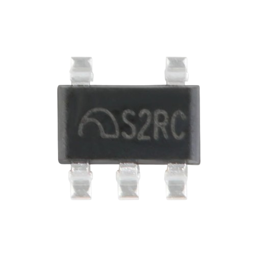
| Package Type | TO-263 or SOIC-8 |
Pin Configuration and Descriptions
The LDOME6211 is available in an 8-pin SOIC package. Below is the pinout and description:
| Pin Number | Pin Name | Description |
|---|---|---|
| 1 | VIN | Input voltage supply (6V to 40V). Connect to the power source. |
| 2 | GND | Ground pin. Connect to the circuit ground. |
| 3 | EN | Enable pin. A high signal enables the driver; a low signal disables it. |
| 4 | DIM | Dimming control input. Accepts PWM or analog signals for brightness control. |
| 5 | ISET | Current set pin. Connect a resistor to set the output current. |
| 6 | LED+ | Positive terminal for the LED string. |
| 7 | LED- | Negative terminal for the LED string. |
| 8 | TEMP | Thermal feedback pin. Monitors temperature for thermal protection. |
Usage Instructions
The LDOME6211 is straightforward to use in LED driver circuits. Follow the steps below to integrate it into your design:
Step 1: Power Supply
- Ensure the input voltage (VIN) is within the range of 6V to 40V.
- Use a decoupling capacitor (e.g., 10µF) between VIN and GND to stabilize the input voltage.
Step 2: Setting the Output Current
- Connect a resistor (RSET) between the ISET pin and GND to set the desired output current.
- Use the formula below to calculate RSET: [ RSET (\Omega) = \frac{1.2V}{I_{OUT} (A)} ] For example, to set an output current of 500mA: [ RSET = \frac{1.2}{0.5} = 2.4 , \Omega ]
Step 3: Connecting LEDs
- Connect the LED string's positive terminal to the LED+ pin and the negative terminal to the LED- pin.
- Ensure the total forward voltage of the LED string is less than the input voltage.
Step 4: Dimming Control (Optional)
- For PWM dimming, apply a PWM signal (0-100% duty cycle) to the DIM pin.
- For analog dimming, apply a DC voltage (0-2.5V) to the DIM pin.
Step 5: Thermal Management
- Ensure proper heat dissipation by using a heatsink or placing the component on a PCB with good thermal conductivity.
- Monitor the TEMP pin for thermal feedback if needed.
Example: Using LDOME6211 with Arduino UNO
Below is an example of controlling the LDOME6211 using an Arduino UNO for PWM dimming:
// Example: Controlling LDOME6211 brightness with Arduino PWM
// Connect the DIM pin of LDOME6211 to Arduino pin 9

const int dimPin = 9; // PWM pin connected to DIM pin of LDOME6211

void setup() {
  pinMode(dimPin, OUTPUT); // Set pin 9 as an output
}

void loop() {
  // Gradually increase brightness
  for (int brightness = 0; brightness <= 255; brightness++) {
    analogWrite(dimPin, brightness); // Write PWM signal to DIM pin
    delay(10); // Small delay for smooth transition
  }

  // Gradually decrease brightness
  for (int brightness = 255; brightness >= 0; brightness--) {
    analogWrite(dimPin, brightness); // Write PWM signal to DIM pin
    delay(10); // Small delay for smooth transition
  }
}
Best Practices
- Use a properly rated resistor for RSET to avoid overheating.
- Ensure the input voltage is stable and within the specified range.
- Avoid exceeding the maximum output current to prevent damage to the LEDs or the driver.
Troubleshooting and FAQs
Common Issues and Solutions
| Issue | Possible Cause | Solution |
|---|---|---|
| LEDs are not lighting up | Incorrect wiring or insufficient input voltage | Verify all connections and ensure VIN is within the 6V-40V range. |
| LEDs flicker during operation | Unstable input voltage or poor dimming signal | Add a decoupling capacitor to VIN or check the PWM/analog dimming signal. |
| Driver shuts down unexpectedly | Overheating due to poor thermal management | Improve heat dissipation with a heatsink or better PCB design. |
| Output current is not as expected | Incorrect RSET value | Recalculate and replace RSET with the correct resistor value. |
FAQs
Can I use the LDOME6211 for RGB LEDs?
- Yes, but you will need one LDOME6211 driver per color channel (Red, Green, Blue).
What happens if the temperature exceeds 150°C?
- The LDOME6211 will automatically shut down to protect itself from damage.
Can I use a potentiometer for dimming?
- Yes, you can connect a potentiometer to the DIM pin for analog dimming.
Is the LDOME6211 suitable for battery-powered applications?
- Yes, as long as the battery voltage is within the 6V-40V range.
By following this documentation, you can effectively integrate the LDOME6211 into your LED projects and ensure reliable performance.